DT-01822A
Kiosk ePassport Reader User Guide
© 3M 2007 All rights reserved.
7
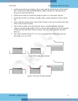
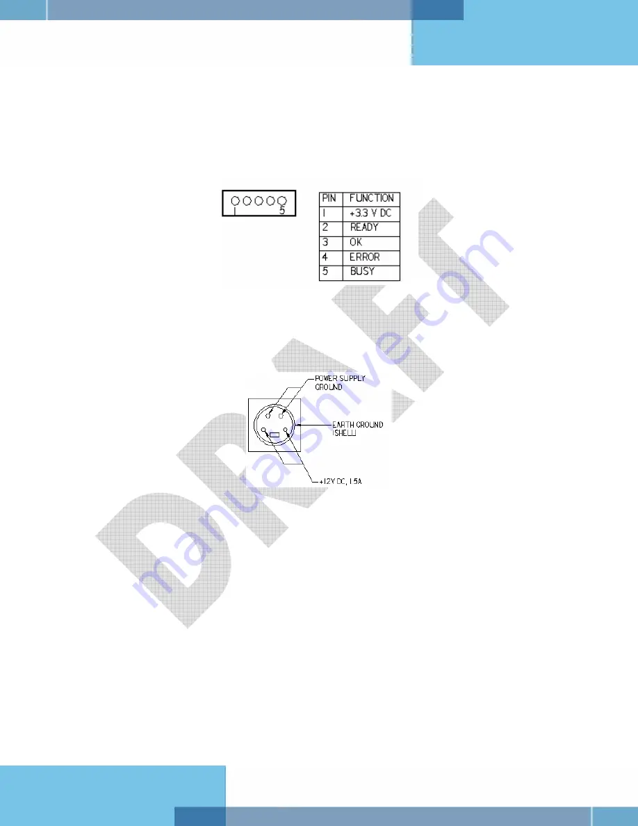
A five-pin header is provided to drive a remotely-located status LED display on the kiosk, or to
allow the kiosk hardware to monitor the status of the reader. The reader connector is designed to
mate with Molex p/n 0874390600 housing and 87421 crimp terminals. The remote status LED’s
are assumed to have a common anode at +3.3V. The reader will pull connector pins to ground
through 200-ohm resistors, supplying approximately 7.5mA per LED. Pin assignment of this
connector is shown in the following figure.
Figure 5: Status LED Connector
Power Connector
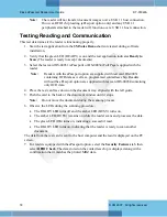
The reader must be connected to a UL-Listed DC power supply capable of pro12V DC
at 1.1A. The connector pinouts are shown in the following figure.
Figure 6: Power Supply Connector
Mounting Points
The readers contain eight M4 threaded mounting bosses, two on each side and four on the
bottom, as shown in the following figure. The preferred mounting points are on the bottom. If the
side mounting points are used, care must be taken in the design of the kiosk mounting surfaces to
ensure that tensile stress is not placed on the reader chassis. The M4 hardware should protrude
into the reader chassis no more than 8mm.
At the factory all eight bosses are filled with threaded plastic inserts to prevent dust entry into the
enclosure.
Summary of Contents for Kiosk ePassport Reader PV35-02 Series
Page 8: ......


