3D Systems, Inc.
23
p/n: 15-D99, rev. C
4.7
Floor Specifications
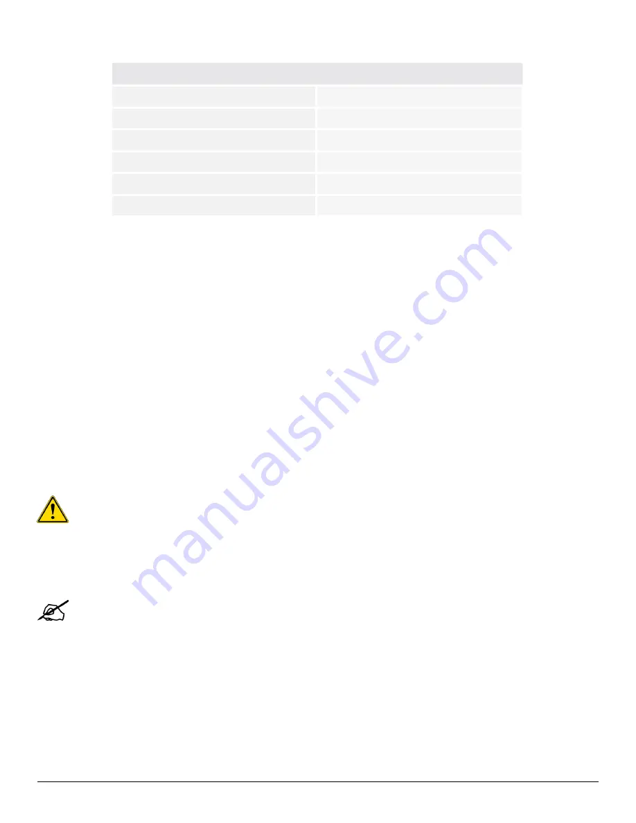
REQUIREMENTS
COMMENTS
Thickness
152.4 mm (6”)
Material
Concrete
Vibration-free
Required
Ground floor installation
Preferred
Grounded conductive or anti-static
Anti-static floor mats can be used
Minimum overall floor loading
1300 kg/m² (270 lbs/ft²)
To ensure part quality and accuracy, choose a ground floor location which will minimize vibration. Normal or incidental
environmental vibrations should not affect the DMP Flex 350 system; however, the area should be isolated, either via location or
some other physical or mechanical means, from any significant internal or external vibration sources such as heavy machinery,
airplanes, or trains, which could cause unacceptable shock or vibration levels.
It is recommended that the location is equipped with conductive or dissipative flooring (metal/unpainted concrete) with a floor
resistance of less than 108
ohms. As an alternative anti-static floor mats may be used.
The process chamber can be anchored to the floor with anchor bolts. For more details on this, please refer to the paragraph
below. Contact 3D Systems immediately if the floor in your facility is less than 152.4 mm (6 inches) thick. It may be necessary to
specify a different anchor bolt for your facility.
In the free-standing configuration a counterweight (
p/n: 151501
) must be bought from 3D Systems to counter the weight of the
printer door.
4.7.1 Drill Locations for Anchor Bolts
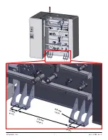
For safety reasons, the DMP Flex 350 printer should be anchored to the floor. 3D Systems provides 130 mm long bolts type
MKT SZ-B 24/50.
The customer is responsible for drilling the connection holes, and thus should provide proper drilling
equipment
. The holes for the bolts must be 24 mm in diameter. It is recommended the holes are drilled with a diamond drill so
the sides of the holes are clean and smooth.
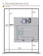
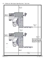
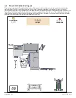
1. Use the dimensions mentioned in the previous pages to determine the position of the machine in your facility.
2. Mark the position for all four holes as shown in the image on the next page.
Caution: The holes cannot be located within 76 mm (3 inches) of a seam or an expansion joint.
3. Use a 24 mm diamond bit to drill each hole 130 mm deep.
4. Clean each hole with a long brush or compressed air.
5.
Close off holes with a piece of tape to avoid accumulating dirt inside the hole.
Note: See next page for the exact dimensions needed to drill holes.

