5-3
Configuration Example
Network requirements
z
A user logs in to the switch through Web.
z
The banner page is desired when a user logs into the switch.
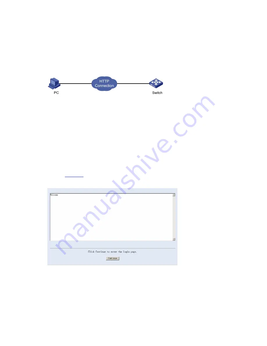
Network diagram
Figure 5-3
Network diagram for login banner configuration
Configuration Procedure
# Enter system view.
<Sysname> system-view
# Configure the banner
Welcome
to be displayed when a user logs into the switch through Web.
[Sysname] header login %Welcome%
Assume that a route is available between the user terminal (the PC) and the switch. After the
above-mentioned configuration, if you enter the IP address of the switch in the address bar of the
browser running on the user terminal and press <Enter>, the browser will display the banner page, as
shown in
Figure 5-4
.
Figure 5-4
Banner page displayed when a user logs in to the switch through Web
Click <Continue> to enter user login authentication page. You will enter the main page of the
Web-based network management system if the authentication succeeds.
Enabling/Disabling the WEB Server
Follow these steps to enable/Disable the WEB Server:


