background image

Copyright © 2022 Nortek Security & Control LLC

17

Connect an External Alarm Sounder

The terminal block inside the 2GIG EDGE Panel includes two (2) solid-state bell terminals (BELL+/BELL-) for an external alarm sounder. An external 
alarm sounder is typically housed outside of a property, in a location that will attract the most attention, in order to scare unwanted intruders 
away with an audible alarm. When choosing a location for the sounder, ensure it is protected from harsh weather (either housed indoors or in a 
weatherproof box). It should also be mounted in a location where the siren can be easily heard by occupants.


»

If you are installing or replacing a new external sounder:

 First, install or replace the external sounder in the desired 

location. Once in place, route the wiring to the panel’s terminal block.


»

If an external sounder is already installed: 

First, disconnect power to the external sounder. Ensure Panel is disconnected from 

power and battery, then route the sounder’s existing wiring to the panel’s terminal block.

IMPORTANT:

 The 2GIG EDGE Panel is designed to connect to Solid-State Relay sounders only. To avoid damage to the output, do NOT 

connect an Electromechanical Relay bell to the BELL+ or BELL- position on the panel’s terminal block. In addition, bell output is only 
provided when the panel’s power supply is connected to an AC power source.

To connect an external alarm sounder to the 2GIG EDGE Panel:

1 . 

Install the sounder in a secure, weatherproof location where it can be easily heard.

2 . 

Disconnect the sounder from its power source.

3 . 

Ensure the 2GIG EDGE Panel is disconnected from both the 
AC power source and the backup battery.

4 . 

Route the wiring from the sounder through the wiring 
cutout in the back of the 2GIG EDGE panel.

5 . 

Connect the sounder’s wires to the BELL+ and BELL- 
positions on the panel’s terminal block.

6 . 

Connect the battery and AC power source.

NOTE:

 For sounders with low current consumption, low 

current relays, or in the event that the Piezo Sounder 
produces a humming sound or noise, install an 820Ω 
resistor in parallel with the sounder.

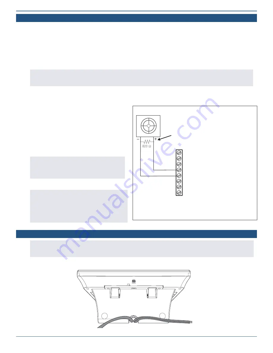
Wiring Diagram—Bell Output

TIP: 

After the installation is complete, navigate to the 

Panel Programming menu to configure siren supervision. 
This lets the system notify both the user and the Central 
Station if the wire between the external alarm sounder 
and 2GIG EDGE Panel is cut. By default, this setting is 
turned OFF. See “Q212: Siren supervision time.”

The bell output can be programmed for supervision 
to detect if the wire to the bell is cut.

1

: GND

2

: AUX+

3

: GND

4

: BELL+

5

: BELL–

Supervised bell output
6 - 12VDC @ 200mA 
Maximum

6

: ZONE 1

7

: ZONE 2

8

: GND

Use Solid State Sounders ONLY.

Do NOT connect to an electromechanical bell.

Piezo/Siren

For sounders with low current  consumption or if 
the Piezo siren on the sounder produces a hum 
or noise, install an 820Ω resistor in parallel with 
the sounder. 

Optional Desktop Kit

NOTE:

 If necessary, the Panel can be mounted on a stand that can be placed on a flat surface, such as desk or counter using the 

2GIG Desktop Kit. Keep in mind that this option may affect compliance with state or regional codes. For additional information see the 
installation instructions for the 2GIG-EDG-DESK.

Optional 2GIG Desktop Kit—Rear View

Summary of Contents for EDGE

Page 1: ...TM 2GIG EDGE Security Smart Home System INSTALLATION GUIDE ...

Page 2: ... ATTIC MOUNT ANTENNA OPTIONAL 13 Mount Antenna 13 Install Jumper 14 Connect the Antenna 15 MOUNT THE PANEL 16 Mount the Backplate to a Wall 16 Connect an External Alarm Sounder 17 To connect an external alarm sounder to the 2GIG EDGE Panel 17 Optional Desktop Kit 17 Connect the Hardwire Loops 18 To install the hardwire loop wiring for the contact sensors 18 Connect the Power Wires 19 Terminal Bloc...

Page 3: ... Q125 LED Mode Control 47 Q126 Commercial Burglary Support 47 Timers Delays Counts 48 Q201 Exit delay in seconds 48 Q202 Entry delay 1 in seconds 48 Q203 Entry delay 2 in seconds 48 Q204 Alarm cancel time in minutes 48 Q205 Alarm abort window transmission delay 48 Q206 Burglary bell cutoff time 48 Q207 Fire bell cutoff time 49 Q208 Swinger shutdown count 49 Q209 Cross sensor timeout in seconds 49 ...

Page 4: ...Q513 RF low battery reports to CS 55 Q514 Sensor low battery restore reports to CS 55 Q515 System disarmed reports to CS 55 Q516 System armed reports to CS 55 Q517 Alarm restore reports to CS 55 Q518 Smart test reports 56 Restore the Factory Default Settings 56 2GIG EDGE REMOTE KEYPAD 56 PANEL PROGRAMMING 57 Sensor Programming Reference 57 Sensor Equipment Type 58 Equipment Codes 58 Transmission I...

Page 5: ...health and property DANGER This notation is used to indicate hazardous situations which if not avoided will result in serious injury or death WARNING This notation is used to indicate potentially hazardous situations which if not avoided could result in serious injury or death CAUTION This notation is used to indicate a potentially hazardous situation which if not avoided could result in minor or ...

Page 6: ...Communication AT T Verizon Long Term Evolution with 4G connectivity to the AT T and Verizon network Mobile System Control Easily control your system remotely utilizing your Remote Service Provider app Dual Path WiFi Cell System communicates to the network using both the cellular LTE and Wi Fi If one service goes down for any reason the other is always available and communicating Enjoy free and fas...

Page 7: ...ity and convenience as it allows them to walk through their structure without concern of tripping alarms for areas they d like to keep secure and armed Some examples of partitioning use cases include Arming a section of a room that contains a safe that contains gun collections or valuables These areas may not be accessed as frequently as the other areas in the room Having a portion of the home des...

Page 8: ...ating the panel s firmware C Piezo Sounder An internal 85 dB Piezo Sounder D Terminal Block Two terminal blocks with screw terminal positions for connecting the 2GIG EDGE Panel to electrical power DC IN DC IN hardwire loops wired zones ZONE1 ZONE2 solid state output BELL BELL and an open collector output OCL1 OCL2 E Backup Battery A backup battery used with the 2GIG EDGE Panel to extend service du...

Page 9: ...ners to ensure sensor batteries and wireless signals are tested at least once a year Depending on the specific installation systems may also be installed with one or more of the following 2GIG accessories Kits Keypads 2GIG Control Panel Desktop Kit 2GIG EDGE Remote Keypad 2GIG PAD1 Antennas 2GIG External Mount Antenna Sensors Peripherals 2GIG Thin Door Window Surface Contact 2GIG Recessed Door Win...

Page 10: ...C to 49 C 32 F to 120 F No altitude range limitations have been reported while transporting the 2GIG EDGE Panel PLANNING THE INSTALLATION Choose the Location for the Panel s Backplate Before installing the system the first step is to create an installation plan for the premises Next determine the mounting location for all system components including the 2GIG EDGE Panel and all sensors If the syste...

Page 11: ...ngth Minimum signal strength required 90 dBm To ensure the system and sensors are placed appropriately review the following illustration Control Panel Location Relative to Sensors CORRECT Centrally Locate Control Panel INCORRECT Sensors at the other end of the house might be too far away Control Panel Location Height CONTROL PANEL Basement CORRECT Mount Control Panel as HIGH above earth level as p...

Page 12: ... 72 National Fire Alarm and Signaling Code National Fire Protection Association Batterymarch Park Quincy MA 02269 Where NOT to Install a Smoke Alarm Do NOT install a smoke alarm in a location where the normal ambient temperature is below 40 F 4 4 C or higher than 100 F 37 8 C Do NOT install a smoke alarm directly above a sink shower or bathtub Do NOT mount a smoke alarm next to a door or window af...

Page 13: ...steps Mount Antenna 1 Mount the antenna plate as high as possible on a wall or in the attic A 2 Drop the antenna s 10 foot cable down to the 2GIG EDGE Panel B 3 Remove the four screws that secure the back panel and then carefully remove the back cover from the panel 4 Feed the Antenna cable through the main opening in the panel s mounting plate then set the assembly aside ...

Page 14: ...ct the Jumper Wire from the vacated terminal to the vacant Jumper terminal adjacent to the Antenna Terminal The jumper wire should snap into place on each terminal 3 Insert the exposed wire from Step 1 into the available foam holder to isolate it from exposure to other board components Terminal Exising Wire Disconnected Jumper Terminal Jumper Terminal Antenna Terminal Jumper Wire Insert Wire ...

Page 15: ...ol LLC 15 Antenna Wire Clip Antenna Terminal Connect the Antenna 1 Connect the antenna terminal to the board terminal You should feel it snap into place 2 Insert the antenna wire into the plastic clip 3 Secure the back plate to the panel ...

Page 16: ...ctrical wiring if needed 6 Route the barrel connector for the power supply or 2 conductor wire if connecting power to the panel s terminal block through the wiring cutout 7 If you are installing any additional wiring route those wires through the cutout WARNING To avoid serious injury or death while wiring the terminal block connections do NOT connect the panel s power supply to a power source Alw...

Page 17: ...t the sounder from its power source 3 Ensure the 2GIG EDGE Panel is disconnected from both the AC power source and the backup battery 4 Route the wiring from the sounder through the wiring cutout in the back of the 2GIG EDGE panel 5 Connect the sounder s wires to the BELL and BELL positions on the panel s terminal block 6 Connect the battery and AC power source NOTE For sounders with low current c...

Page 18: ...s means the circuit on the contact switch is closed when the magnets are aligned on the door window contact When armed the 2GIG EDGE Panel activates an alarm signal when it detects that the door or window is no longer in the normally closed state Normally Open N O Used for Normally Open N O circuits This means the circuit on the contact switch is open when the magnets are aligned on the door windo...

Page 19: ...ength meters 22 AWG 50 15 2 20 AWG 80 24 4 22 AWG 2 pairs 19 AWG equivalent 110 33 5 18 AWG 125 38 1 Connecting the power supply to the 2GIG EDGE Panel 1 Locate an unswitched wall outlet for the plug in power supply Do NOT connect the power supply to the outlet at this time 2 Route 2 conductor power wire from the plug in power supply through the wiring cutout on the backplate of the 2GIG EDGE Pane...

Page 20: ...e outlet 4 After connecting or wiring the DC power supply on the panel connect the backup battery see below Connect the Backup Battery 5 Ensure the backup battery is properly seated in the chassis The battery s label should be facing up and the battery s connector wire should be on the left with the wire running in the empty space between the battery compartment 6 Insert the wired battery pin into...

Page 21: ...arefully remove the back cover from the panel 2 Carefully detach the power cable from the battery to be replaced Detach 3 Take hold of the battery and carefully detach it from the panel Note You may need to apply a reasonable amount of force to separate the battery from the adhesive that holds it in place Remove Battery 4 Peel off the adhesive strip from the back of the new battery Adhesive Strip ...

Page 22: ...Installation Guide for the 2GIG EDGE Security Panel 22 4 Insert the new battery and attach the power cable Connect Power 5 Replace the back cover Replacing the Battery continued ...

Page 23: ... 5 6 7 8 9 10 11 12 13 14 Position Label Description 1 GND DC OUT GND DC OUT 2 AUX 5VDC 500mA Max 3 GND Ground Low Side Hardwire Zone 4 Bell 5 14VDC 200mA Max NOTE Bell Output is only active when the 2GIG Edge Panel is powered by the AC power source 5 Bell 6 ZONE 1 Hardwire Loop Zone 1 7 ZONE 2 Hardwire Loop Zone 2 8 GND Ground Low Side Hardwire Zone 9 DC IN 14 VDC Power Input Only provides power ...

Page 24: ...d Contact UL NOTE Wiring for all wired sensors and annunciators must use UL Listed low voltage Class 2 or better grade wire Sensor and display voltages must comply with Class 2 low voltage requirements systems shall be installed in accordance with ANSI NFPA 72 CSA C22 1 CAN ULC S302 and CAN ULC S301 Hardware loops can be programmed as normally open or normally closed End of Line Resistors are opti...

Page 25: ...o the wall receptacle NOTE For compliance with ANSI NFPA 70 National Electric Code in the United States you must install the power supply retaining bracket To install the wall bracket and connect the AC power supply 1 Locate a wall outlet for the plug in power supply Do NOT connect the power supply to the receptacle IMPORTANT When selecting a wall outlet never connect the plug in power supply to a...

Page 26: ...DATE Firmware Update Available from USB Device NOTE Firmware Update Available from USB Device message appears for approximately 10 seconds If you are not able to tap the Update button in the message in that time you can alternately tap the System Settings button or the Firmware Update button in the system icons area Then enter the Master User Code and then tap Firmware Update to start the update p...

Page 27: ...e you must enter an Installer Code The factory default code is 1561 REMINDER Change the installer code before finishing installation To access the Installer Toolbox 1 Tap the Settings icon 2 Tap KEYPAD 3 Enter 1561 to gain access to the panel settings then tap Installer Toolbox 4 Scroll down then tap the Installer Toolbox icon ...

Page 28: ...2 Tap to expand the list 3 Tap to select the desired equipment code from the list 4 Tap to move to the next option Sensor Type 1 Tap Sensor Type 2 Tap to expand the list 3 Tap to select the appropriate sensor type from the list NOTE You can also use the keypad to enter the two digit code to display a Sensor Type 4 Tap to move to the next option Sensor Equipment Type if needed If you selected 04 In...

Page 29: ...e next option Sensor Loop 1 Highlight Sensor Loop 2 Choose Loop 1 Loop 2 or Loop 3 NOTE To determine the appropriate loop number see the Installation Instructions included with the sensor or peripheral 3 Tap to move to the next option Voice Descriptor Create a voice descriptor for the sensor or peripheral 1 Highlight Voice Descriptor 2 Tap Edit Voice Descriptor to reveal the keypad 3 Enter the fir...

Page 30: ...em two Hard wired zones and the Panel Glassbreak detector To get started navigate to the Installer Toolbox Tap Panel Programming then tap the Built In Zones option Selecting a Wired Built In Zone 1 On the left side of the Built In Zone screen review the list of zones 2 Tap one of the available zones to highlight it A zone is available when it appears in gray text 3 Tap EDIT ZONE Sensor Type 1 High...

Page 31: ...descriptor 8 Tap to move to the next option Sensor Chime 1 Highlight Sensor Chime 2 Choose the desired chime from the list The default setting is Disabled Smart Areas Assignment 1 Highlight Smart Areas Assignment 2 Choose a Smart Area Partition for the zone 3 Tap to move to the next option Transmission Delay 1 Highlight Transmission Delay 2 Choose Enabled or Disabled 3 Tap to move to the next opti...

Page 32: ... the first few letters of the desired word 4 Tap the matching word above the keypad 5 Repeat the steps above to enter a phrase 6 Tap Done 7 Review the voice descriptor 8 Tap to move to the next option Sensor Chime 1 Highlight Sensor Chime 2 Choose Enabled or Disabled 3 Tap to move to the next option Smart Areas Assignment 1 Highlight Smart Areas Assignment 2 Choose a Smart Area Partition for the z...

Page 33: ...erial Number 1 Highlight Serial Number 2 Tap Learn to enter Learning Mode 3 The 7 digit TX ID listed on the product is detected 4 Press any button on the keyfob for three 3 5 seconds The Sensor Received message appears if successful TIP Along with Learning Mode you also have the option to manually enter the 7 digit TX ID using the keypad 5 Verify the on screen serial number matches the keyfob s 7 ...

Page 34: ...to the next option Fob Can Disarm 1 Highlight Fob Can Disarm 2 Under Fob Can Disarm choose Enabled or Disabled 3 Tap to move to the next option Arm with No Entry Delay 1 Highlight Arm with No Entry Delay 2 Choose Enabled or Disabled 3 Tap to move to the next option Fob Output 1 Highlight Fob Output 2 Choose one of these options Disabled This deactivates the option Toggle Output Press the Auxiliary...

Page 35: ...be connected to the access point of the 2GIG EDGE Panel before starting keypad programming See Network Settings page 38 Keypad 1 Swipe up to move through the list of keypads 2 Tap to select one of the available keypads then tap Edit Keypad Make sure the Keypad Used setting is highlighted 3 Under Keypad Used choose Enabled or Disabled 4 Tap to move to the next option 5 Tap PAIR KEYPAD The panel wil...

Page 36: ...ptor 1 Highlight the Voice Descriptor setting 2 Tap ADD VOICE DESCRIPTOR to reveal the touchscreen keypad 3 Enter the first few letters of the desired vocabulary word 4 Tap the matching vocabulary word above the touchscreen keypad to select it 5 Repeat the steps above to enter the desired phrase for the keypad 6 Tap Done 7 Review the voice descriptor Reset Keypad Next Keypad Tap Reset Zone to eras...

Page 37: ...tions 4 The panel will prompt when an Image Sensor is found 5 Tap OK 6 Image Sensor details are displayed 7 Tap to move to the next option After Image Sensors have been added to the 2GIG EDGE Panel in Wireless Zones programming the Image Sensor details will be displayed in Image Sensor settings The Image Sensor will be displayed with the following Zone number MAC address of Image Sensor Firmware V...

Page 38: ...ps above to enter a phrase 5 Tap DONE 6 Tap to move to the next option Sensor Chime 1 Tap Sensor Chime to assign a sound to the Image Sensor 2 Tap to move to the next option Sensitivity 1 Tap Sensitivity then select High Normal or Low 2 Tap to move to the next option Smart Area Assignment 1 Tap Smart Area Assignment then assign the Image Sensor to a particular Smart Area zone S1 S2 S3 or S4 2 Tap ...

Page 39: ...ised 1 Tap Sensor Supervised 2 Tap Enabled or Disabled Reset Keypad Next Keypad Tap RESET ZONE to erase all the programmed settings for the zone Tap NEXT ZONE to program another Image Sensor Panel Programming Network Settings Wireless Network 1 Tap an available Wireless Network Name 2 Correctly enter the assigned network password to connect 3 Tap to go back to the Network Settings menu 4 Enter net...

Page 40: ...to join a network not shown in the list 1 Return to the Wireless Network screen 2 Tap JOIN OTHER NETWORK 3 Enter the wireless network name then tap NEXT 4 Select the Security Type and Security Mode then tap NEXT 5 Enter the password WPS Tapping WPS allows you to connect securely to routers that support WPS 1 Tap WPS on 2GIG EDGE Panel 2 Tap Connect 3 Locate and press the WPS on your router 2GIG ED...

Page 41: ...rt Home Manual for the 2GIG EDGE Security Panel for complete use and setup information View All Devices Displays all Z Wave Smart Home Devices connected to the panel Add Device 1 Tap Add Devices The Listening for Devices to Add page appears 2 Walk to and trigger the device on the network When the system discovers a device the system automatically adds it and the Adding Device message appears 3 Tap...

Page 42: ...ting Tap each button and respond Yes or No to each question If any of the tests fail please contact your dealer for assistance Disable Sounder Press YES to disable the Sounder The panel will beep The siren will be silent for 30 minutes or until it is re enabled manually Cell Radio Test Status At the Radio Status screen tap Test Cell Radio Status for Signal Strength Serial Number Subscriber ID Regi...

Page 43: ...ange installer code Defines the unique four digit code for installers to use when accessing the Installer Toolbox See Installer Toolbox page 27 Choose one of these options 1561 This is the factory default setting Enter a unique code If you change the Installer Code be sure to remember it so you can access the system later The Installer Code must be unique from the Master User Code and all other us...

Page 44: ...you specify This gives the Cellular Radio Module in the 2GIG EDGE Panel the ability to automatically dial the Central Station and connect with an operator after an alarm sounds Once connected with the Central Station people on the premises can communicate with the operator using the built in speaker and microphone Choose one of these options next page Disabled Disable 2 way voice Stay on line Defa...

Page 45: ...arms from any Smart Area will alert and sound at the 2GIG EDGE Panel Main Panel Smart Area Only Only alarms in Smart Area 1 will alert at the 2GIG EDGE Panel alarms in Smart Areas 2 4 will only alert on keypads assigned to those areas NOTE With both options alarms for all Smart Areas are visible by entering the Smart Areas Screen via the Home Screen button Q112 Z Wave siren mode Configures the sys...

Page 46: ...d Q116 Allow quick exit Configures the system to allow users to quickly exit the premises while the system is armed in Stay Mode When this feature is turned ON and a user taps Arm Stay a Quick Exit button appears on the System Armed screen When a user taps Quick Exit the system starts the Exit Delay countdown and the user must exit the premises before the countdown expires After the countdown expi...

Page 47: ...ent to the Central Station Q123 Cross sensor zones 99 100 Defines the alarm verification requirement for a cross sensor zone A cross sensor zone is comprised of two wireless sensors and both sensors must be violated before the system activates the alarm This means that before a cross sensor zone can activate an alarm the sensors for both Wireless Zone 99 and Wireless Zone 100 must be violated If o...

Page 48: ...ire a slightly longer entry time are programmed as an Exit Entry 2 door For example a back side or garage entry door When a user enters the premises while the system is armed the Entry Delay 2 countdown starts The 2GIG EDGE Panel beeps once every two 2 seconds during the countdown Choose one of these options 30 240 Seconds Choose a value between 30 and 240 seconds 45 Seconds For compliance with AN...

Page 49: ...d for Wireless Zone 99 and Wireless Zone 100 If both sensors are violated within the amount of time specified here the system activates an alarm If only one of the sensors is violated during the timeout interval the system transmits a trouble report to the Central Station and does not activate an alarm NOTE For the timeout to affect the system the Cross Sensor Zones feature must also be enabled on...

Page 50: ... on the Alarm screen The system sounds a loud patterned warning siren after the user activates a panic alarm Silent Panic Turns the feature ON This makes the Panic button visible on the Alarm screen The system sounds a silent panic alarm with no warning siren after the user activates a panic alarm Q302 Fire emergency key Configures the system to show or hide the Fire button on the Alarm screen of ...

Page 51: ...NSI SIA CP 01 2010 you must set Open Collector Output 1 to 11 Follows Internal Sounder Alarm NOTE If you enabled a keyfob auxiliary button to trigger the panel s Open Collector 1 make sure this question is set to 00 Disabled Program a Keyfob Choose one of these options Code Open Collector Output Code Open Collector Output 00 Disabled 06 Activated on Burglary Alarm 01 Activated When Armed 07 Activa...

Page 52: ... after a cellular radio network failure Disabled Turns the reporting feature OFF The 2GIG EDGE Panel will not transmit a trouble report to the Central Station after a cellular radio network failure Q404 Broadband network failure time in minutes Configures the system to display a trouble alert on the touchscreen when the system loses its broadband network connection The number of minutes you specif...

Page 53: ...if a tamper switch is triggered while the system is armed You have these options Enabled The system activates a trouble condition Disabled The system does not activate a trouble condition CS Reporting Q501 CS lack of usage notification time in days Configures the system to monitor itself for lack of usage If the system is not armed for the number of days you specify here an inactivity report is se...

Page 54: ...entral Station NOTE Bypass setting on Alarm com monitoring settings supersedes Q507 Bypass restore reports to CS Q508 Force bypass reports Configures the system to transmit a report to the Central Station when a user force bypasses a sensor while the system is armed You have these options Enabled The system transmits a report to the Central Station Disabled The system does not transmit a report to...

Page 55: ... system Choose one of these options Enabled The system transmits a report to the Central Station Disabled The system does not transmit a report to the Central Station NOTE Arming setting on Alarm com monitoring settings supersedes Q515 System disarmed reports to CS Q516 System armed reports to CS Configures the system to transmit a report to the Central Station when the system is disarmed by a use...

Page 56: ...t in days 0 255 all non test reports occurring during normal operations will restart the periodic test report timer for example alarm restore trouble etc Periodic test reports are only sent when the 2GIG EDGE Panel has not reported in any way to the Central Station Choose one of these options Enabled The system transmits a report to the Central Station Disabled The system does not transmit a repor...

Page 57: ... type is for interior sensors such as motion detectors interior doors and other sensors that detect human presence inside the protected premises This type of sensor is called a follower due to its action when the system is armed in the Away mode After the exit delay expires and the system is armed if an interior follower sensor is triggered an instant alarm will occur If an exit entry delay sensor...

Page 58: ...ilent triggering the burglary alarm with perimeter doors and windows that will not be used to enter or exit the protected premises while the system is armed The Control Panel s sounder and the bell output will not activate An instant silent alarm will occur when this type of sensor is triggered with the system armed in either the Stay or Away mode 32 Remote Device Special Zone with Wireless Repeat...

Page 59: ...ion Detector 0475 Existing Glass Break Detector 0616 Existing Smoke Detector 0692 Existing CO Detector 0708 Existing Heat Sensor 0556 Existing Flood Temp Sensor 1061 Tilt Sensor 0470 HW R D W 5818MNL 0637 Honeywell D W 5816 0530 HW PIR 5894PI 0533 HW PIR 5890 0519 HW Glass Break 5853 0589 HW Smoke 5808W3 0557 HW Heat Sensor 5809 0624 HW Flood Sensor 5821 Transmission ID TXID Required for all wirel...

Page 60: ...01 Gas 102 Gate 265 Girl s 278 Glass 103 Glass Break 104 Grill 307 Guest 105 Gun 106 H Hall 107 Hallway 108 Hanging 109 Hang Up 110 Heat 111 High 112 Home 113 Hot Tub 297 House 114 I Ice 115 Image 279 Image Sensor 280 In Law 298 Inside 116 Instant 117 Interior 118 Intrusion 119 Is 120 J K Key 121 Keyfob 122 Keypad 123 Kids 124 Kitchen 125 L Laundry 126 Leak 305 Left 127 Level 128 Library 129 Light...

Page 61: ...equired for all wireless zones Sensor Supervised Choosing this setting Enabled Default Enables the sensor supervision feature Disabled Disables the sensor supervision feature Sensor Chime Required for all wireless and wired zones Sensor Chime Setting Disabled Default Voice Only Ding Dong 1 with Voice Ding Dong 2 Ding Dong 2 with Voice Ding Dong 1 Ding Ding Ding Ding with Voice Ding Dong 3 Ding Don...

Page 62: ...le siren after two way audio Yes No No System Configuration 43 Q107 Smart Areas Enabled Disabled Disabled System Configuration 43 Q108 Z Wave feature Disabled and Hidden Disabled but Visible Enabled Enabled with Local Scenes Hidden Enabled System Configuration 44 Q109 Master user can access Z Wave setup Enabled Disabled Disabled System Configuration 44 Q110 Smart Home Controls require master code ...

Page 63: ...led System Configuration 46 Q201 Exit delay in seconds 45 120 45 120 Seconds 60 Seconds Timers Delays Counts 47 Q202 Entry delay 1 in seconds 30 240 30 240 Seconds 30 Seconds Timers Delays Counts 47 Q203 Entry delay 2 in seconds 30 240 30 240 Seconds 45 Seconds Timers Delays Counts 47 Q204 Alarm cancel time in minutes 5 255 5 255 Minutes 5 Minutes Timers Delays Counts 47 Q205 Alarm abort window tr...

Page 64: ...iguration 50 Q308 Open collector 2 output 00 Disabled 01 Activated when Armed 02 Activated when Disarmed 03 Activated on FTC 04 Activated on Supervision 05 Activated on Radio Fault 06 Activated on Burglary Alarm 07 Activated on Fire Alarm 08 Activated on Any Alarm 09 Activated on Any System Trouble 11 Follows Internal Sounder Alarm 12 Follows Exit Entry Beeps 00 Disabled Panel Configuration 50 Q30...

Page 65: ...09 AC loss reports to CS Enabled Disabled Enabled Reporting 53 Q510 AC restore reports to CS Enabled Disabled Enabled Reporting 53 Q511 System low battery reports to CS Enabled Disabled Enabled Reporting 54 Q512 System low battery restore reports to CS Enabled Disabled Enabled Reporting 54 Q513 RF low battery reports Enabled Disabled Enabled Reporting 54 Q514 Sensor low battery restore reports to ...

Page 66: ...nt Alert Keyfob Disarming After Alarm Keyfob Arm Disarm Confirmation Q119 Alert on disarm with keyfob after alarm Q120 Keyfob arm disarm confirmation 4 2 4 4 Remote Arming Key Fob Arming Q119 Alert on disarm with keyfob after alarm 4 3 4 5 Remote Disarming Key Fob Arming Q120 Keyfob arm disarm confirmation 4 2 5 1 Abort Window Abort Window Dialer Delay Q205 Alarm abort window transmission delay 4 ...

Page 67: ...sposal will help to conserve natural resources and ensure that it is recycled in a manner that protects human health and the environment For more information about where you can drop off your waste equipment for recycling please contact your local city office or your household waste disposal service or the shop where you purchased the product WARNINGS Limitations of Alarm Products This product sho...

Page 68: ...Nortek Security Control LLC All rights reserved 2GIG is a registered trademark of Nortek Security Control LLC 10025596 Rev D A L A R M D E A L E R I N F O R M A T I O N Company Name Your Account Number Installation Date ...

Reviews: