ϰ
sϴ͘Ϯϭ
/ŶƐƚĂůůĂƟŽŶDĂŶƵĂů
1
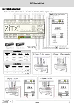
Connecting the system
All system components are wired to the control unit or to its
expansion modules.
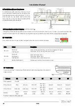
It is advisable to locate the equipment preferably in a high
place away from metal masses and conductive elements;
place the control unit in a protected place that can only be
accessed by authorized personnel and with appropriate
Tools for opening and subsequent handling of the equip-
ment in question.
Place at a height of approximately 1.5 m, avoiding di-
rect heat sources and unwanted air currents
Avoid to location the thermostats near metal masses and
conductive elements.
1. Supply voltage, (230VAC/ 50 Hz/
1)
2. 10kOhm NTC temperature sen-
sors (see location according to
type of machine)
3. 12 VDC output voltage for wired
thermostats
4. Control LEDs, to monitor the
status of the control unit
5. 433/434 MHz Radio
transmission antenna (only
in ZITY-RC control units)
6. Digital inputs, potential-free inputs
7. RS485 local communication
bus. For wired thermostats and
expansion modules.
8. RS485 local communication
bus, for communication with
equipment interfaces (connect
in parallel with the previous
bus)
9. RS485 remote communication
bus for home automation com-
munication/ BMS or NetBox
(MODBUS RTU-SLAVE protocol)
10. 24 VDC outputs for control of
motorised zone dampers (maximum
2 dampers per zone) (24Vdc –200
mA)
11. Control relays of the climate-control
equipment (see connection
depending on the type of equipment).
Maximum current 6A
12. Thermostats: Wired or via radio
Fig.1 Connecting all ZONING SYSTEM components in the ZITY control unit.
Содержание Zity
Страница 1: ...W K Ky d d d...
Страница 2: ...s D...
Страница 5: ...s dz h 1 1 A Direct expansion system with via radio thermostats and NetBox gateway 1 2 3...
Страница 6: ...s D Direct expansion system with wired thermostats and NetBox gateway Z s s Z E t KD z Ed K Ed 1 2 3...
Страница 24: ...W K Ky d...


