ϭϬ
sϴ͘Ϯϭ
/ŶƐƚĂůůĂƟŽŶDĂŶƵĂů
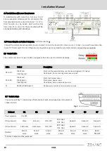
1.4 Installations with more than 6 zones
In installations with more than 6 zones, 1 or 2
zone expansion modules will be connected. The
first expansion module controls zones 7 to 12. A
third module can be added, which will control
from zone 13 to zone 18. These modules
ZLOO EH
FRQQHFWHGYLDWKHXQLWVORFDOEXV
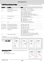
1.6 Control LEDs
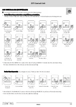
The control unit has 2 rows of LEDs (red/green) that are used to monitor its status.
LEDs
Colour
Description
R1 to R7
Static red
Flashing red
Static red: The associated relay is active (see paragraph 2.11 relays)
Flashing red: Error or learning mode (see error list)
Z1 to Z6
Static red
Static green
Flashing red
Static red: Damper closed
Static green: Damper open
Flashing red: Zone communication error
Tx
Random flashing red
Flashes every time radio communication arrives
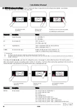
1.7 Control relays
The control unit has 7 control relays. The function of each relay depends on the protocol
chosen in Sw1.
Protocol
R1
R2
R3
R4
R5
R6
R7
Direct expansion
On/OFF
4 Pipe Fancoil
Cold valve
Heat valve
ON / OFF
OFF=Heat
ON= Cool
Speed 1
Speed 2
Speed 3
Radiant
Zona 1
valve
Zona 2
valve
Zona 3
valve
Zona 4
valve
Zona 5
valve
Zona 6
valve
Boiler
ON/OFF
Ύϭ͗ZĞůĂLJϭŽƵƚƉƵƚŵƵƐƚďĞũƵŵƉĞƌĞĚ
2 Pipe Fancoil
Valve
Valve (1)
ON / OFF
OFF=Heat
ON= Cool
Speed 1
Speed 2
Speed 3
&ŝŐ͘Ϯ
ŽŶƚƌŽůƌĞůĂLJƐ
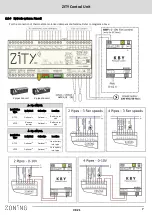
1.5 Connecting the motorized dampers. Parallel connection.
Connect the motors of each regulator to wire clamps 1 to 6 on the board (10). Use a red (+) / black (-) wire with a section of be-
tween 0.75 mm
2
and 1.0 mm
2
. If there are two regulators per zone (maximum recommended), connect them in parallel
Содержание Zity
Страница 1: ...W K Ky d d d...
Страница 2: ...s D...
Страница 5: ...s dz h 1 1 A Direct expansion system with via radio thermostats and NetBox gateway 1 2 3...
Страница 6: ...s D Direct expansion system with wired thermostats and NetBox gateway Z s s Z E t KD z Ed K Ed 1 2 3...
Страница 24: ...W K Ky d...


