


Page 7
3.
Secure the backplate to the box using the screws
that came with the electrical box.
4.
Drill out a ½" hole and insert the round seal
supplied with the kit. A remote cable will run
through the middle hole of the backplate and
into the electrical box.
Figure 2. Controller Components
2.5
Installation of the Backplate on a Flat
Wall
CAUTION
Do not expose the user interface to direct sunlight. Too
much direct sunlight will darken the LCD screen, and it
will no longer be readable.
1.
Turn off the pump at the control panel.
2.
Turn off all electrical power to the pump at
the main junction box or at the circuit breaker
providing electrical power to the pump.
WARNING
ELECTRICAL SHOCK HAZARD
Turn off all switches and the main breaker in the ePump™
electrical circuit before starting the procedure. Failure to
comply may cause a shock hazard resulting in severe
personal injury or death.
3.
A minimum of two (2) fasteners (installer
supplied) are required when installing to a flat
wall to hold the controller securely.
4.
The backplate has ten (10) mounting holes to
choose from. Only drill out the backplate holes
that will be used. See Figure 2.
5.
Mark the hole locations on the wall and use the
fastener to secure the backplate to the wall.
6.
At the bottom of the backplate, cut the two
(2) tabs out with an appropriate tool, such as a
Stanley knife, and route the cable through the
open channel.
2.6
Connection to the Jandy ePump™
Variable Speed Pump
The following steps provide the procedure for
installing the controller to a Zodiac ePump™ variable
speed pump.
1.
Turn off all switches and the main breaker that
supplies power to the pump.
WARNING
ELECTRICAL SHOCK HAZARD
Turn off all switches and the main breaker in the ePump™
electrical circuit before starting the procedure. Failure to
comply may cause a shock hazard resulting in severe
personal injury or death.
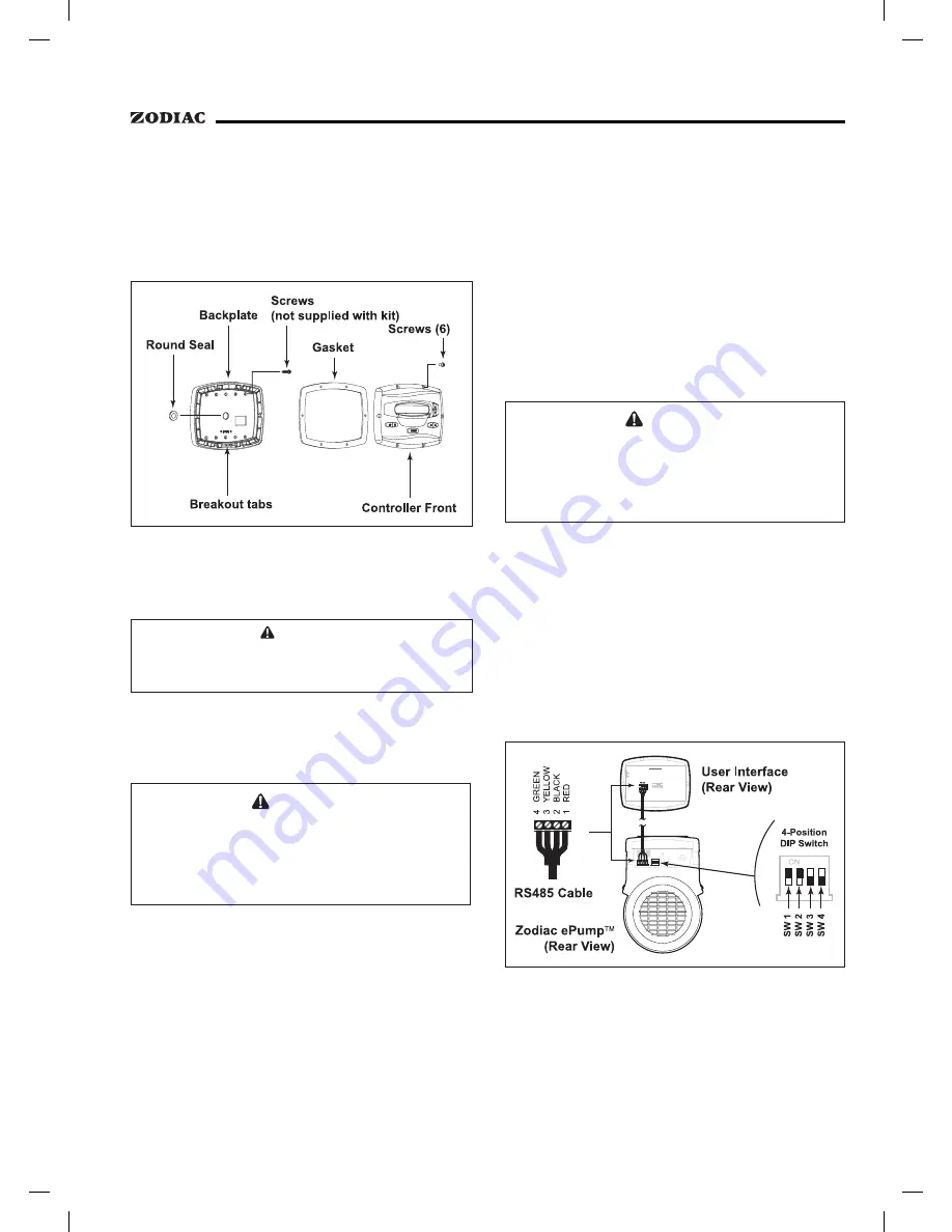
2.
Attach the four (4) wires in the RS-485 cable
to the RS-485 connector. Make sure the colors
match the positions on the User Interface. See
Figure 3.
3.
Turn on all switches and the main breaker
feeding power to the pump.
4.
Verify the operation of the controller. If the
controller displays
FAULT PUMP NOT
CONNECTED
, re-check the wiring and the
DIP switch address setting on the pump.
Figure 3. Wiring the User Interface to the Zodiac
ePump™
Variable Speed Pump
2.7
Zodiac ePump™ Variable Speed
Pump Switch Settings
For the ePump™, the 4-position dip switch is
located at the rear of the pump, as shown in Figure 3.


