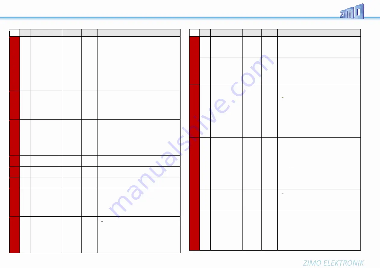
Page 62 MS-SOUND decoders MS440 to MS990
CV
Denomination
Range
Default Description
3.12
#140
Distance controlled
stopping -
Constant Braking Dis-
tance
Selection of the
braking occasion
and the
braking behavior
0,
1, 2, 3, 11,
12, 13
0
Activation of distance-controlled stopping (Constant Brak-
ing Distance) as defined in CV #141 instead of time con-
trolled braking as defined in CV #4, for
= 1 automatic stop with ZIMO HLU ("signal-controlled
speed influence") or ABC (signal stop by "asymmetric
DCC signal").
= 2 manual stop by speed controller.
= 3 automatic and manual stopping.
In the above cases (= 1, 2, 3) braking from partial speeds
is delayed so that the train does not "creep" for an unnec-
essarily long time (this is the recommended choice). On
the other hand
= 11, 12, 13 as above, but braking is always initiated as
soon as the train is entering the stopping section.
3.12
#141
Distance controlled
stopping -
Constant Braking Dis-
tance
The braking distance
0 - 255
0
The value in this CV defines the "Constant Braking Dis-
tance". The value suitable for the existing braking dis-
tances must be determined by trial and error; as a guide
can serve: CV #141 = 255 means approx. 500 m in the
prototype (i.e. 6 m in H0), CV #141 = 50 is approx. 100 m
(i.e. 1.2 m for H0).
see also: CV #831 - #833
3.12
#830
Braking distance for-
ward High Byte
0 - 255
0
Extended definition of the Constant Braking Distance:
With CV #830 - #833 a more precise and direction de-
pendent braking distance can now be set. The factor
compared to CV #141 is 1 to 16.
The braking distance to be defined is calculated from:
(256 * High Byte) + Low Byte.
CVs #830 - #833 are only effective if CV #141 = 0.
3.12
#831
Braking distance for-
ward Low Byte
0 - 255
0
3.12
#832
Braking distance
backward High Byte
0 - 255
0
3.12
#833
Braking distance
backward Low Byte
0 - 255
0
3.12
#143
Distance controlled
stopping -
Constant Braking Dis-
tance
Compensation for
HLU method
0 - 255
0
Since HLU is more error-resistant than ABC, no detection
delay is usually necessary; therefore default 0.
3.7
#146
Compensation for
gear backlash during
direction changes in
order to prevent
start-up jolt.
0 - 255
0
= 0: no effect
=1 to 255: in ase the driving direction was changed be-
forehand, the motor spins at minimum rpm for a defined
timespan (according to CV #2) for a specific time and
only starts to accelerate after this time has elapsed.
The time of these “idle rotations” can only be tried; typical
values:
= 100: the motor turns about 1 revolution or a
maximum of 1 second at the minimum speed.
CV
Denomination
Range
Default Description
= 50: about ½ a turn or max. ½ second.
= 200: about 2 turns or max. 2 seconds.
Important: The minimum speed in CV #2 must be config-
ured correctly, so that the train moves perfectly at the
lowest speed step (1).
3.6
#147
#148
#149
Fine adjustment of
the
PID parameters
NOTE
: are adjusted
automatically with
CV #56!
0 - 255
0 - 255
0 - 255
100
10
100
I
ntegral value of the PID-motor regulation,
recommended for „modern“ powertrain: CV #147 = 65
D
ifferential value of the PID-motor regulation,
recommended for „modern“ powertrain: CV #148 = 45
P
roportional value of the PID-motor regulation,
recommended for „modern“ powertrain: CV #149 = 65
3.4
3.6
#151
Reduction of motor
control in consist op-
eration
or
motor brake
(if address NOT in
consist)
Tens digit 1
- 9:
0
The tens digit reduces the motor compensation to 10 -
90% according to the value in CV #58.
= 0: brake not active
= 1 - 9: In case of “zero power supply to the motor”
(Motor PWM = 0) the speed to the desired speed step is
still not reached (speed is still too high), the motor brake
is slowly activated (distributed to 1, 2, ... 8 seconds until
the full effect by short circuit on the motor through the
power amplifier). The higher the value, the stronger the
brake is applied.
= tens digit (1-9): Reduction of the motor regulation if
consist-key is active. The values 1-9 in the tens digits in
CV #151 reduce the control to 10%-90% of the value set
in CV #58.
3.19
#152
Dim Mask 2
Excludes specific
function outputs
from dimming
Addition to
CV #114
and
FO3, FO4 as
Direction outputs
Bits
0 - 5
and
Bit 6,
Bit 7
0
0
... Addition to CV #114.
Bit 0 - function output FO7,
Bit 1 - function output FO8,
Bit 2 - function output FO9,
Bit 3 - function output FO10,
Bit 4 - function output FO11,
Bit 5 - function output FO12.
Bit 6 = 0: “normal“
= 1: Direction bits on FO3, FO4, i.e.
FO3 is switched on when driving backwards,
FO4 is switched on when driving forward.
(for Märklin switch type C)
Bit 7 = 1: direction bit for FO9 when driving forward
3.1
#153
Time limit for
continued driving
without rail signal
0 - 255
0
= 0 (default): Continued driving as long as energy is
available.
= 1 - 255 (tenths of a second): Stopping time if the rail
signal is not received (although supply from energy stor-
age)
5.4
5.6
#154 Various special bits
16
Bit 1 = 1: DIESEL, ELECTRO Drive off immediately even
if playback of idle sound has not yet finished.
Bit 2 = 1: DIESEL, ELECTRO After short stops, wait for
idle sound before driving off.
Bit 4 = 1: STEAM: Two stage compressor (Z1 for fast re-
fill after coming to a stop, Z2 for slow pressure loss
compensation during longer stops).
Bit 7 = 1: Delay start until playback of start-up whistle has
finished.


