PREMIER QUATRO INSTALLATION MANUAL (Fyreye MKII) Firmware Versions: PANEL 1.84 & LOOP 3.70
Doc No: GLT-215-7-1 Issue: 1.36 Author: NJ/TE DATE: 25/05/2017
34
7.1.14 ZONE LABELS
The subdivision of a fire alarm system was explained in Section 3, the Premier Quatro panel being capable of assigning 20 zones.
When a fire is enunciated, the zone number in which the fire is located is indicated on the alphanumeric display. In addition to its
numerical description, a zone can be identified by a text label, e.g. 3
RD
FLOOR WEST EXT. If the installer associates a text label with
each zone of a fire alarm system, this will be displayed on the LCD when a fire is detected. The maximum length of the zone text
label is 18 characters.
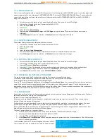
To access the menu for selecting Zone Labels:
Turn the key switch clockwise to the Controls Enabled
Position. The controls Active LED will light.
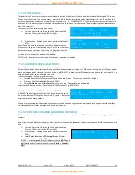
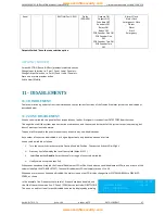
ZONE EDIT
ZONE :<XXX> MODE ENABLE
TEXT :[3RD FLOOR WEST EXT ]
[ - ] [ + ] [Points] [Exit]
Press any key followed by the level 2 password (default is
2222).
Select Zone edit, and then the zone number by either using the
alphanumeric keypad, or the function keys F1 or F2 to increment or
decrement the zone number. Type in the text label between the
brackets on the 3rd line of the display. Selecting F3 allows one or
more points (i.e. devices) to be added to the loop.
ADD POINTS
ZONE : <XXX> LOOP :[1]
RANGE : [001] TO :[001]
[Accept ] [Exit ]
The LCD also indicates the current mode of each zone – enabled or disabled.
7.1.15 ADDRESS LABELS AND ZONES
Premier Quatro is an addressable panel, i.e. it will indicate the address or location of a fire that has been detected. The address
number of each point or device on each loop has already been selected according to its DIP switch setting. The installation engineer
must now assign a label or location for each device, e.g. ROOM 107. A maximum of 20 characters can be used for each label. At the
same time each point can be allocated to a zone.
To access the menu for selecting Address Labels:
Turn the key switch clockwise to the Controls Enabled Position. The controls Active LED will light.
Press any key followed by the Password 2222.
Select
Points
followed by
Edit Point
. For each point the following data can be entered:
Loop Number, Address Number, Zone Number & the Text Label (e.g. ROOM 107)
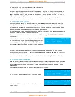
The LCD also indicates the MODE of a point, i.e. ENABLED or
DISABLED, the analogue value (V) that the device is sending to the
panel, and the type. Pressing the
F
keys below [–] and [+], decreases
or increases the address number.
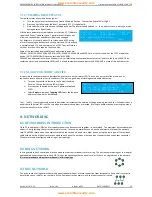
LOOP :<1> ADR :[019] ZONE:[023]
TYPE :MCP MODE :ENABLE V:192
TEXT :[ROOM 107 ]
[ - ]
[ + ] [Exit ]
When a fire is detected, the address label of the device which has been triggered can be displayed by using the keys
►
and
◄
to
scroll through the list of fires detected and stored by the panel.
7.1.16 PLATFORM SOUNDER (SANDWICH SOUNDER)
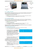
The remote output on a detector is used to switch on a connected remote indicator (LED). It can also be used to trigger a “platform
sounder”
A panel cannot see a platform sounder as it does not communicate with the panel, so the panel needs to be told that the sounder is
fitted.
Turn the key switch clockwise to the Controls Enabled
Position. The controls Active LED will light.
Press any key followed by the level 2 password (default
2222).
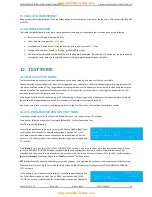
Select
Point
followed by
LED Setup
. Change Platform
sounder field from NO to
YES
.
(NOTE: It is recommended that all detectors that do
NOT
have a
platform sounder fitted are to have it set as
Platform Sounder:
NO
.)
LOOP :<1> ADR :[002] TYPE :MKII-AOH
PLATFORM SOUNDE:[YES]
[ - ] [ + ] [Exit ]
www.acornfiresecurity.com
www.acornfiresecurity.com

