background image

PREMIER QUATRO INSTALLATION MANUAL (Fyreye MKII)                                                                                     Firmware Versions: PANEL 1.84 & LOOP 3.70


Doc No: GLT-215-7-1                                   Issue: 1.36                                  Author: NJ/TE                                  DATE: 25/05/2017 

31 


7.1.2 POWER SUPPLY 

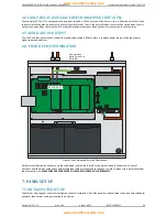
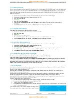
Quatro is normally supplied with an external PSU Charger card.  This is the approved PSU CHARGER option. It can also operate with 
a power supply which is part of the panel’s MOTHERBOARD PCB. This is the MOTHERBOARD CHARGER Option. To ensure that the 
correct fault monitoring is selected, the installer must indicate whether the MOTHERBOARD CHARGER or the PSU CHARGER is 
being used, as follows: 


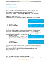
Turn the key switch clockwise to the Controls Enabled Position. The controls Active LED will light.  


Press any key followed by the level 2 password (default is 2222) 


Select the option 

General 


Press 

ENTER


Select the option 

Power Supply 


Toggle between 

Motherboard Charger

 and 

PSU Charger

 (using the 

 and 

 symbols until the correct mode is 

displayed).


Press 

F1 (Accept)

 to accept the selection, or 

F4 (Cancel)

 to retain the previous PSU mode.


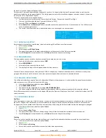
7.1.3 LOOP MANAGEMENT 

The number of loops connected to the panel should be set here. 


Press any key followed by the level 2 password (default is 2222) 


Select the option 

Loop


Press 

ENTER


Select the option 

Loop Management


The panel then displays the 4 loops and whether or not they are installed. Adjust as required. 


Press 

F1 (Accept)

 to accept the selection, or 

F4 (Cancel)

 to retain the previous settings. 


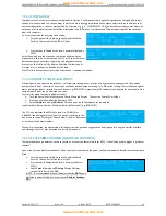
7.1.4 SETTING TIME AND DATE 


Turn the key switch clockwise to the Controls Enabled Position. The controls Active LED will light.  


Press any key followed by the level 2 password (default is 2222) 


Press the 

 key until 

Date-Time

 is highlighted. 


Press the 

ENTER

 key. The date and time can now be entered using the numeric keypad and the directional keys.  


Press 

F1 [Accept]

 to accept a new date and time, or 

F4 [Cancel]

 to leave the date / time unchanged.  


Press 

Cancel

 or 

 until the screen shows 

SYSTEM NORMAL

 or 

FAULT

7.1.5 CREATING AN INSTALLATION NAME 

This can be entered using the PC configuration software. But to enter it manually at the panel:- 
Turn the key switch clockwise to the Controls Enabled Position. The controls Active LED will light.  
Press any key followed by the level 2 password (default is 2222) 
Press the 

 key until 

General

 is highlighted. Select 

General

 then 

Installation Name

. You are now able to enter the site reference 

name of the panel, plus name and telephone number of the installation or Maintenance Company. The site reference name is 
displayed on the top line of the SYSTEM NORMAL screen, on the left hand side. The name and phone number of the maintenance 
company will be alternately displayed with any fault condition of the panel. 

7.1.6 PASSWORDS 

As described earlier in this section, 2 passwords are required to view and set up the configuration on the Quatro panel. These are 
required to increase the security of a site configuration.  

(a) Level 1 or User Passwords (Default 1111) 

Authorised users are allowed to view the panel’s configuration, status and event logs (see section 16). They can also disable 
(section 13) and test (section 14) the panel.  
Each authorised user can be assigned his own 4-digit Level 1 password by the installation / commissioning engineer. The panel 
permits up to 31 unique level 1 passwords, i.e. up to 31 people can have their own unique access to Level 1 data. It is 
recommended that these passwords are assigned during the commissioning of the panel. Changes to these passwords at a later 
date will require a further site visit by the installation engineer.  
The Level 1 password can be changed as follows: 


Turn the key switch clockwise to the Controls Enabled Position. The controls Active LED will light.  


Press any key followed by the level 2 password (default is 2222). 


 Press the 

 key until 

General

 is highlighted.  


Select 

General

 and then 

Password

. You are now able to enter the password for the 1st authorised user. The LEVEL must be 

set to 1 (see top right corner). 

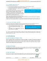
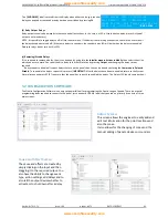
In the example, the 1st user has been assigned a Password of 4321. 
There can be up to 31 user numbers, each with a unique Password. 

CHANGE PASSWORD            LEVEL:    <1> 
USER   :[01] 
PASSWORD:[4321] 
[Accept  ]                  [Exit      ]


www.acornfiresecurity.com

www.acornfiresecurity.com

Содержание Prem1er Quatro

Страница 1: ...e MKII Firmware Versions PANEL 1 84 LOOP 3 70 Doc No GLT 215 7 1 www zetaalarmsystems com Issue 1 36 MKII PROTOCOL ONE TO FOUR LOOPS ANALOGUE ADDRESSABLE FIRE ALARM PANEL INSTALLATION MANUAL www acornfiresecurity com www acornfiresecurity com ...

Страница 2: ...TERNAL LAYOUT 10 3 3 NAVIGATING THE PANEL MENUS 11 3 3 1 NAVIGATING A SET UP SCREEN 11 3 4 CONTROLS 11 3 5 INDICATING DIFFERENT PANEL STATES 12 3 5 1 THE QUIESCENT CONDITION 12 3 5 2 THE ALARM CONDITION 12 3 5 3 THE FAULT CONDITION 13 3 5 4 DISABLEMENT 13 3 5 5 TEST MODE 13 4 DESIGNING THE SYSTEM 14 4 1 DESIGNING THE SYSTEM 14 4 2 RECOMMENDED CABLE TYPES AND THEIR LIMITATIONS 14 4 3 LOOP CALCULATI...

Страница 3: ... 9 REMOTE LED INDICATOR 26 6 4 SETTING THE DEVICE ADDRESS DETECTORS CALL POINTS SOUNDERS AND INTERFACE UNITS 27 6 4 1 SOFT AND HARD PROGRAMMING 27 6 4 2 DIP SWITCH ADDRESS SETTINGS FULL TABLE 27 6 5 FIRE RELAY VOLTAGE FREE CHARGE OVER CONTACTS 29 6 6 FAULT RELAY VOLTAGE FREE CHANGEOVER CONTACTS 30 6 7 AUXILIARY DC OUTPUT 30 6 8 FIELD DEVICE TERMINATION 30 7 PANEL SETUP 30 7 1 INITIAL PANEL SETUP 3...

Страница 4: ...STALLER LEVEL LEVEL 2 45 10 3 CAUSE EFFECT TABLE 46 11 DISABLEMENTS 47 11 1 DISABLEMENT 47 11 2 ZONE DISABLEMENT 47 11 3 DEVICE DISABLEMENT 48 11 4 SOUNDER DISABLEMENT 48 11 5 RELAY DISABLEMENT 49 11 6 DISABLE BUZZER 49 12 TEST MODE 49 12 1 WHY USE TEST MODE 49 12 2 TO PROGRAMME ZONE IN TEST MODE 49 13 FAULT FINDING 50 13 1 LOOP CONTENTS FAULT FINDING 50 13 2 ZONE FAULTS 50 13 3 FALSE ALARMS 51 13...

Страница 5: ...p and away from damp dirty areas e g in a small cardboard box 1 2 SAFETY PRECAUTIONS DURING NORMAL OPERATION OF PANEL NOTE When the Quatro panel is operating normally i e not being tended by service personnel the access door must be closed and locked After locking the key MUST be removed and ONLY held by the responsible person and or the service personnel It must under NO CIRCUMSTANCES be held by ...

Страница 6: ...mmissioned according to our guidelines and the relevant National Standards by an approved and competent person or organization the warranty may become void 2 PANEL SPECIFICATION 2 1 FUNCTIONS REQUIRED BY EUROPEAN STANDARD EN54 PART 2 The Premier Quatro fire alarm control panel provides the following mandatory and optional functions as prescribed by the European standard EN54 Part 2 a Mandatory Fun...

Страница 7: ...witch ON Installer password Configure loops Assign zones Assign Text to each point Modify Alarm Operation Programming Configure network if fitted System Diagnostics LED blink loop Auto check Change passwords Configure RS232 Output if fitted 3b Installer Engineer Open Enclosure Lock Connect wiring during Install Battery check during Maintenance Reset System fault Update Cause Effect programming via...

Страница 8: ...in 26 V DC MAXIMUM LOOP CURRENT 500 mA NUMBER OF LOOPS 4 MAXIMUM NUMBER OF ZONES 250 Zones MAXIMUM LOOP CAPACITY 250 Addresses MAXIMUM LOOP LENGTH 2 km MAXIMUM LOOP RESISTANCE 44 ohm 22 ohms to 22 ohms to MAXIMUM LOOP CAPACITANCE 500nF MAXIMUM LOOP BAUD RATE 1024 Bits Per Second MAXIMUM NETWORK SIZE 32 nodes MAXIMUM DISTANCE BETWEEN NODES 1 km CABLE TYPE Fire Proof 2 core screen 1 5 mm 2 ALPHA NUM...

Страница 9: ...oc No GLT 215 7 1 Issue 1 36 Author NJ TE DATE 25 05 2017 8 2 5 FUSE SPECIFICATIONS Power Supply Controller PCB Fuse Label Rating Description A_Fuse 2 5A PSU Output Channel A B_Fuse 2 5A PSU Output Channel B Link Fuse 8A Battery fuse A B www acornfiresecurity com www acornfiresecurity com ...

Страница 10: ... Fuse Rating Description F1 NOT USED NOT USED F2 F 500 mA 24V Aux Supply Fuse F3 NOT USED NOT USED F4 F 500 mA Conventional Sounder Circuit SND 1 F5 F 500 mA Conventional Sounder Circuit SND 2 F6 F 5 A IN PS1 Fuse Power from PSU Controller F7 F 5 A IN PS2 Fuse Power from PSU Controller Fuses 1 3 are used for the Motherboard Charger option www acornfiresecurity com www acornfiresecurity com ...

Страница 11: ...ed with other Quatro panels or repeaters with up to 32 panels per network It has a simple Intuitive Action Programming for configuring sounder relay operations It has an optional add on TCP IP card that allows the panels recent events to be viewed in a web browser It has an advanced Alarm management graphics package works with TCP IP card It has an easy to use configuration software package which ...

Страница 12: ...entered directly with leading zeros if necessary Text fields Use up down cursors to move the cursor in the string 3 4 CONTROLS The panel contains the following mandatory controls They can only be operated when the key on the front of the panel has been turned clockwise from OFF to CONTROLS ENABLED The CONTROLS ACTIVE LED indicates that the controls have been enabled START STOP SOUNDERS This contro...

Страница 13: ...one in fire In the example the first alarm was in Zone 3 Zone 3 is the Second Floor The 2nd line indicates the most recent zone in fire The format is the same as line 1 The most recent fire occurred in Zone 5 which is the Fourth Floor FIRST ALARM Z003 SECOND FLOOR LAST ALARM Z005 FOURTH FLOOR ZONES IN FIRE 004 POINTS IN FIRE 010 PRESS OR TO SCROLL Two or more zones in alarm Line 1 indicates the fi...

Страница 14: ...d the general disablement LEDs are lit steady 10 12 13 13 51 DISABLED ZONES 001 001 Z001 Ground Floor In this example the addressable point at loop 1 address 1 is disabled It is a call point General disablement LED is lit Zone is not lit because the whole zone is not disabled 10 12 13 13 51 DISABLED POINTS 001 001 MCP 1 001 Front Door In this example sounder circuit 1 on the motherboard has been d...

Страница 15: ...better the description the easier it is to locate in the event of an alarm The panel allows 22 characters It may be necessary to use abbreviations to achieve the required label Keep the design of the system and any changes to it well documented This makes it easier to trace any configuration errors during installation commissioning 4 2 RECOMMENDED CABLE TYPES AND THEIR LIMITATIONS The use of Miner...

Страница 16: ...ly a battery calculation spreadsheet is available Please contact your distributor for details 4 6 CHOOSING AUDIBLE VISUAL WARNING DEVICES There are a number of options for Audible visual Devices that can be directly or indirectly connected to one of the 4 loops on Premier Quatro A maximum of 64 loop powered sounders are permitted on each loop which can be either stand alone sounders or sounders in...

Страница 17: ...nect to the EVACS 16 system It sees each channel of the EVACS as a voice sounder so the panel has control over the individual channels They will be programmed as part of the usual ACTIONS programming for alert and evacuate tones 4 6 7 ADVANTAGES AND DISADVANTAGES OF DIFFERENT SOUNDER TYPES SOUNDER TYPE ADVANTAGE DISADVANTAGE Conventional Wide range of devices Devices tend to be cheaper Immediate s...

Страница 18: ... an open circuit reading Also make sure that the screen earth has continuity and is not showing an open circuit Now test between the core making sure there is no short circuit repeat this test between screen and screen 3 ADDRESS DEVICES When you have checked the loop cables you can now number all the devices and connect loop 1 to the panel Turn the panel on and autosearch loop 1 Once the panel has...

Страница 19: ...ing the building It should be fitted to a sturdy wall that will not flex unnecessarily It should ideally be mounted at eye level in order for it to be viewed without need of a ladder It should be installed in a dry weatherproof place preferably NOT in direct sunlight It should be easily accessible so that the responsible person can perform their regular fire alarm checks 5 2 FIXING THE BACK BOX TO...

Страница 20: ...he Knock out cable entries can be easily removed by Tapping with a suitable screwdriver or chisel from outside the control panel box Take care not to dent or deform the metal enclosure If a grommet is removed fill the hole with a brass cable gland If any knockout is removed but subsequently not used it should be covered up The 230V AC Mains cable must be fed into the enclosure via one of the cable...

Страница 21: ...rself with the fire alarm panels controls 5 6 CONNECTING THE BATTERIES SOUNDER CIRCUIT DETECTION LOOP MAINS IN EARTH BAR Figure 4 Battery location and connection details To calculate the exact requirement use the equation in section 17 STANDBY BATTERY REQUIREMENTS The two batteries are wired in series The ve of one battery is connected to the red battery lead The ve of the other battery is connect...

Страница 22: ...nother zone The screen cable at each end of the loop not shown below must be connected to the Panel s earth bar Figure 5 Example of addressable loop wiring top connections to loop cards bottom 6 2 ADDRESSABLE LOOPS Pre commissioning check At this stage it is important to remember devices e g detectors call points sounders etc should not be connected yet if a high voltage Megger type tester is to b...

Страница 23: ...ing terminals are used for connecting the call point 2 x Negative in terminals note if you only connect to the negative in terminals then the isolator is bypassed 1 x Positive in terminal 1 x Positive out terminal 1 x Negative out terminal note if used puts the isolator in circuit 1 x Earth terminal used to connect the cable screen 6 3 2 MKII detectors All types Base connection Negative out termin...

Страница 24: ...lows Terminal L1IN is ve Blue Terminal L2 is ve Brown These are the only two connections required Deep Base MKII CB D Common Base MKII CB 6 3 3 ZAI MI Input Module The end of line resistor value is 20KΩ and the trigger resistor value is 1kΩ 6 3 4 ZAIO MI Input output Module The end of line resistor value is 20KΩ and the trigger resistor value is 1KΩ www acornfiresecurity com www acornfiresecurity ...

Страница 25: ...er circuit is 10KΩ When using the ZASC make sure the PSU being used has a fault output relay so that in the event of a power supply fault it is reported to the control panel Note All Power Supplies used on fire alarm systems MUST comply with EN54 part 4 6 3 6 ZAZM MI Conventional Zone Module The ZAZM powers the conventional zone from the addressable systems loop so no external power supply is requ...

Страница 26: ...ol Connecting the sounder is done using the terminals in the back box of the device Please refer to the above diagram 6 3 8 Sandwich Sounder The sandwich sounder has no wiring to connect as it just clips straight on to a standard base It will run as a platform sounder using no address and is controlled by the detector fitted to it It can also be given an address via the handheld programming tool m...

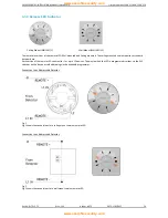
Страница 27: ...nted version requires a standard detector base Each version of the remote LED can monitor 1 or up to 12 devices The way in which the LED is programmed is either via the DIP switches on the device or soft addressing via the handheld programmer Connection to an Addressable Detector Fig 1 Fig 1 shows the connections for a ceiling mount version remote LED Connection to an Addressable Detector Fig 2 Fi...

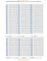
Страница 28: ...L TABLE ADDRESS SWITCHES ADDRESS SWITCHES ADDRESS SWITCHES 1 2 3 4 5 6 7 8 1 2 3 4 5 6 7 8 1 2 3 4 5 6 7 8 0 N O T U S E D 43 OFF OFF ON OFF ON OFF ON ON 86 ON OFF OFF ON OFF ON OFF ON 1 OFF ON ON ON ON ON ON ON 44 ON ON OFF OFF ON OFF ON ON 87 OFF OFF OFF ON OFF ON OFF ON 2 ON OFF ON ON ON ON ON ON 45 OFF ON OFF OFF ON OFF ON ON 88 ON ON ON OFF OFF ON OFF ON 3 OFF OFF ON ON ON ON ON ON 46 ON OFF ...

Страница 29: ...122 ON OFF ON OFF OFF OFF OFF ON 37 OFF ON OFF ON ON OFF ON ON 80 ON ON ON ON OFF ON OFF ON 123 OFF OFF ON OFF OFF OFF OFF ON 38 ON OFF OFF ON ON OFF ON ON 81 OFF ON ON ON OFF ON OFF ON 124 ON ON OFF OFF OFF OFF OFF ON 39 OFF OFF OFF ON ON OFF ON ON 82 ON OFF ON ON OFF ON OFF ON 125 OFF ON OFF OFF OFF OFF OFF ON 40 ON ON ON OFF ON OFF ON ON 83 OFF OFF ON ON OFF ON OFF ON 126 ON OFF OFF OFF OFF OFF...

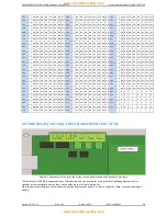
Страница 30: ...ON ON OFF ON ON OFF OFF 244 ON ON OFF ON OFF OFF OFF OFF 159 OFF OFF OFF OFF OFF ON ON OFF 202 ON OFF ON OFF ON ON OFF OFF 245 OFF ON OFF ON OFF OFF OFF OFF 160 ON ON ON ON ON OFF ON OFF 203 OFF OFF ON OFF ON ON OFF OFF 246 ON OFF OFF ON OFF OFF OFF OFF 161 OFF ON ON ON ON OFF ON OFF 204 ON ON OFF OFF ON ON OFF OFF 247 OFF OFF OFF ON OFF OFF OFF OFF 162 ON OFF ON ON ON OFF ON OFF 205 OFF ON OFF OF...

Страница 31: ...rt low power requirements 450mA max A separate power supply will be required for higher current applications 6 8 FIELD DEVICE TERMINATION S S ER R E Connect loop Earth Screens to Earth Bar Figure 7 Connecting cables to the Quatro panel All cables should enter the enclosure via the cable gland and the cable shields must be connected to the earth bar Figure 7 illustrates how the mains cable and an a...

Страница 32: ...configuration software But to enter it manually at the panel Turn the key switch clockwise to the Controls Enabled Position The controls Active LED will light Press any key followed by the level 2 password default is 2222 Press the key until General is highlighted Select General then Installation Name You are now able to enter the site reference name of the panel plus name and telephone number of ...

Страница 33: ...im to always have your loop quality at 100 0 As the quality of communications decreases the chance of the system giving out false alarms or faults increases It can also cause the response from real events to become delayed 7 1 9 ENABLE USB CONFIG This will be selected when using the Quatro Configuration Software or Loop Inspector In order to allow the panel to communicate with a computer via its U...

Страница 34: ...his illustrates the command structure in a menu tree flowchart of the control keys 7 1 13 CONFIGURING THE LOOPS Turn the key switch clockwise to the Controls Enabled Position The controls Active LED will light Press any key followed by the level 2 password default is 2222 The display changes to the view indicated in the yellow box to the right Select Loop by pressing ENTER or or and then Autosearc...

Страница 35: ...ected according to its DIP switch setting The installation engineer must now assign a label or location for each device e g ROOM 107 A maximum of 20 characters can be used for each label At the same time each point can be allocated to a zone To access the menu for selecting Address Labels Turn the key switch clockwise to the Controls Enabled Position The controls Active LED will light Press any ke...

Страница 36: ...ss This is also a good way of tracking down double addresses Turn the key switch clockwise to the Controls Enabled Position The controls Active LED will light Press any key followed by the level 2 password default 2222 Select Points followed by Toggling LED Select the loop and address of the point to be checked The and commands can be used to decrement or increment the address of the point being s...

Страница 37: ... only one node set as controller on the network Network Filter This determines whether this node reports all network events or just those from a specific network address Node search This should be performed from the controller panel The panel configures the network and displays the results The 3 possible configurations are Ring All nodes are connected as a ring Recommended configuration As there a...

Страница 38: ... in a master slave topology Multiple slaves can share the same bus but only one master can be in the line at the same time Master can communicate with a specific device peer to peer or with broadcast frames Modbus defines the communication format including command data and checksum Quatro Modbus uses RTU frames These frames use silences of 3 5 chars and a CRC of 16 bits Data size is 8 bits Quatro ...

Страница 39: ...0 FOR MORE INFORMATION ON USING THE MODBUS PLEASE REFER TO THE MODBUS REGISTERS MANUAL Doc No GLT 256 7 2 8 6 REPEATER PANEL The Repeater Panel is used to remotely indicate the status of all CIE s that are connected on the same network The general fire and fault LED indications are repeated on the Repeater Panel An alphanumeric display provides further fire fault data The Repeater also has its own...

Страница 40: ... apply to a detector alarm in Zone 1 and will ignore all other alarms in Zone 1 Multiple point alarm means that at least 2 points devices in Zone 1 must be activated before the programmed Effects occur The Fault option will trigger cause effects if there is a fault in Zone 1 NOTE If a zone range is selected for Multi Pt Alarm it will set up a multi point alarm in each zone within the range The pan...

Страница 41: ...and outputs can be selected from 4 categories Point Zone Loop and Panel Example of Selecting a Logic Event New Logic The following example shows LOGIC No 2 top right of LCD being selected The Quatro is programmed to only activate the panel sounders with a 10 second delay when points address 7 8 on loop 1 detect a fire This will be to setup the 1st event Select Num of Events 2 MAX 10 EVENTS Select ...

Страница 42: ...he DAY MODE will be active when the day mode is inactive the NIGHT mode will take over Once these settings have been selected press Next to confirm Select the zone range to have the two stage delays apply too and for how many seconds Delay 1 2 will last Press Select and return the home screen If the mode has been successfully set up then either Night Mode or Day Mode shall be displayed When using ...

Страница 43: ...his same location by pressing Output and changing the delay time as required If a user needs to disable all current delays that are on the panel then this can be done by entering the User menu Delays Disable To re enable the delays repeat this process IMPORTANT After the delays have been re enabled return to the System Normal screen and press RESET to ensure that the panel has correctly re enabled...

Страница 44: ... it to the required output Same with cause and affects you have the ability to change event type action settings add delays and to also tell the output device whether to active or shut down after a delay You can also change the number of events needed for the panel to go into alarm Additional Features The software also allows for the download of event logs and to print off loop and cause and effec...

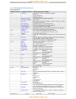
Страница 45: ...SELECTION COMMENT Zones Show Displays zone details Show En Zones Indicates enabled zones Show Dis Zones Indicates disabled zones Show Test Zones Displays zones in test mode Enable Enables zones in range x to y Disable Disables zones in range x to y Test Zones in range x to y are changed to test mode enables disables sounders in zones in test mode Point Show Shows loop address zone type mode analog...

Страница 46: ...der is fitted Toggling LED Activates LED selected point to locate devices on a loop Actions New Add a new cause effect action See Section 9 1 Modify Modify an existing Action New Logic Add a new logic event action See section 9 1 2 Modify Logic Modify an existing logic action Class Change Configure an I O to act as a class change input Disable relays Configure an I O to disable all relay outputs D...

Страница 47: ...a date to print events from that date to present day Date Time Date xx xx xx Time xx xx Date Time Setup 10 3 CAUSE EFFECT TABLE ACTIONS NEW See also Section 9 1 Input Selection Input Type Selection 1 Selection 2 Options Point Loop 1 4 Address 1 to 250 Alarm Zone Range 1 250 To 1 250 General Alarm MCP Alarm Detector Alarm Multiple Point Alarm Fault Loop Range 1 4 To 1 4 General Alarm Panel General ...

Страница 48: ...e user needs the rest of the system to continue running but doesn t want spurious false alarms The panel will respond in the usual manner to any events in any non disabled zones Any number of zones can be disabled but it is good practice to only disable one zone at a time A zone can be disabled as follows Turn the key switch clockwise to the Controls Enabled Position The controls Active LED will l...

Страница 49: ...ay changes from SYSTEM NORMAL to DISABLED POINTS as shown In the example line 2 indicates that a total of 5 points have been disabled and the 1st of these is shown on line 3 The 1st disabled device is an MCP which is located on loop 1 at address 97 with the text label ENTRANCE Each disabled point can be displayed by pressing the control buttons F1 and F2 which correspond to the previous disabled p...

Страница 50: ...and the Alarm sounders will operate for a further 10 seconds If an Alarm occurs on a zone that is not programmed to test the Fire Alarm Panel will continue to operate as normal 12 2 TO PROGRAMME ZONE IN TEST MODE Turn the key switch clockwise to the Controls Enabled Position The controls Active LED will light Press any key followed by the Level 1 password default1111 Select Zones then Test The LCD...

Страница 51: ... more devices This will cause the indicating LEDs for all devices with this address to flash Old Call Points Sounders and some I O units will not be indicated as they have no panel controlled LED to light up An alternative method to find a double address is to AUTOSEARCH the loop and check through REPORTS to see if there is a DAD listed This gives a TYPE LOOP REPORT i e the total number of each de...

Страница 52: ...eplacing 13 4 SUPPLY FAULTS LOSS OF BATTERY POWER OR LOW BATTERY VOLTAGE Check battery fuse Check that battery connections are secure Check battery voltage should be around 26 27V Check that the two batteries are connected in SERIES to give double the voltage of 1 battery on its own Check the charger fuse LOSS OF MAINS POWER Check mains fuse Check that main power is present Check charger fuse LOSS...

Страница 53: ...UT DISABLEMENTS FAULTS section of the panel 13 8 OUT OF SERVICE FAULTS If the system is in a condition in which it is unable to detect a fire or sound the alarm for example if a loop is being configured this is indicated to the User by lighting the Out of Service LED 13 9 NETWORK FAULTS Token Lost This normally means that a panel is become missing in the network Check that there are no breaks in t...

Страница 54: ...m log see example For a general fault line 2 is simply a description of the fault and there is no information on line 3 The size of the Fault log is 1024 Test Log 512 This category indicates events that occur to devices contained in zones which are in the test mode The LCD display is identical to that of the Alarm log 512 test events can be stored All Log 4096 This category stores all Alarm and Fa...

Страница 55: ... 48 Fyreye MKII Addressable Xtratone Sounder MKII AXT 0 65 N A 4 5 64 Fyreye MKII Addressable Xtratone Sounder Beacon MKII AXTB 2 3 N A 20 3 20 Fyreye MKII Addressable Xtratone Flasher MKII AXF 0 6 N A 5 5 48 Sandwich Sounder Base MKII SSB 0 65 N A 5 5 64 Remote Indicator LEDs MKII Addressable Remote LED Indicator Wall MKII ARL W 0 5 N A 5 32 MKII Addressable Remote LED Indicator Ceiling MKII ARL ...

Страница 56: ...op Quatro panel with 80 Fyreye Extra Addressable Optical Smoke Detectors 15 Zeta Addressable Manual Call Points 20 Zeta Addressable Securetone 2 Sounders and the required standby is 24 hours It will need to operate in alarm for hour Calculate the battery size required TALM 0 5 Hr IALM SND 20 x 0 004 0 08A TSBY 24 Hr IQP 0 20A IAP 0 19A IQL 80 x 0 00044 15 x 0 001 20 x 0 0005 0 0602A IALM IALM SND ...

Страница 57: ... Steel QT 3 SS Premier Quatro 4 Loop Analogue Addressable Fire Alarm Panel In Stainless Steel QT 4 SS Premier Quatro 1 Loop Analogue Addressable Fire Alarm Panel In Stainless Steel W Printer QT 1P SS Premier Quatro 2 Loop Analogue Addressable Fire Alarm Panel In Stainless Steel W Printer QT 2P SS Premier Quatro 3 Loop Analogue Addressable Fire Alarm Panel In Stainless Steel W Printer QT 3P SS Prem...

Страница 58: ...ion 14 2 Mentioned 13 1 should have been 14 1 Added better explanation of selecting test mode with sounders 1 33 14 1 2013 Corrected EOL in sounder connection drawings from 10K to 4k7 1 34 14 8 2015 Removed Standard Protocol Added Loop Management Loop Added Alarm Tone Setup Loop Added Flasher Operation Loop Added Engineering Loop Added Disable by Zone Sounders Added Enable by Zone Sounders Added P...

Страница 59: ... 2002 A2 2006 EN54 4 1997 A1 2002 A2 2006 Control and indicating equipment for fire detection and fire alarm systems for buildings Premier Quatro QT 1 QT 2 QT 3 QT 4 Provided options Output to fire alarm devices Delays to outputs Fault signals from points Disablement of addressable points Test condition Other Technical Data See Doc Premier Quatro Product file held by the manufacturer www acornfire...

Отзывы: