BNP
®
6012 and 7212 SUCTION BLAST CABINETS
Page 4
© 2019 CLEMCO INDUSTRIES CORP.
www.clemcoindustries.com
Manual No. 27723, Rev. B 04/19
1.6.1 CDC-1 Dust Collectors:
Shown in Figure 1, the
collector is available for 900 cfm models. The single-filter
cartridge is cleaned by using a manually controlled pulse
of compressed air. Dust collects in a 5-gallon dust drum,
which must be frequently emptied. CDC-1 Dust
Collectors are standard with BNP cabinets with 900 cfm
reclaimers unless an optional RPC-2 or RPH-2 Dust
Collector is ordered at time of purchase. Refer to manual
number 28225.
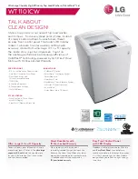
1.6.2
RPC-2
Dust Collectors:
Shown in Figure 2, this
collector is available for 900 cfm models for use with
BNP-6012 and 7212 cabinets. Dual-filter cartridges are
automatically cleaned by a timed, periodic pulse of
compressed air. Dust collects in the drawer, and it must
be frequently emptied. Refer to manual number 22788.
1.6.3
RPH
Dust Collector:
The RPH-2 (900 cfm and
RPH-3 (1200)cfm) are set up and operates the same as
the RPC-2, as shown in Figure 2, but instead of a dust
drawer the collector sits atop a hopper, which provides
additional dust storage and empties into a 30-gallon
drum. An RPH is standard with 1200 cfm models. Refer to
manual number 21449.
Figure 2
1.6.4 HEPA (high-efficiency particulate air)
Filter:
Optional HEPA afterfilters provide additional filtration
and must be used with a reverse-pulse cartridge
collector when removing toxic coatings, heavy metals, or
any other toxic materials. Refer to the applicable dust
collector manual noted in Paragraph 1.1.1 for the HEPA
option.
1.7
Nozzle Options
1.7.1
Unless otherwise specified at the time of
purchase, the cabinet is provided with a No. 5 (5/16"
orifice) ceramic nozzle and No. 5 (5/32" orifice) air jet.
Optional, more durable tungsten carbide and boron
carbide nozzles are available and are shown under
BNP
Gun and Feed Assembly in Section 9.3.
Use a boron
carbide nozzle when blasting with aggressive media, as
noted in Section 1.9.4.
1.8
Reclaimer Options
1.8.1
A 900 cfm pull-thru reclaimer utilizes a CDC-1
reverse-pulse dust collector or optional RPC-2 or RPH-2
dust collector.
A 1200 cfm reclaimer utilizes a RPH-3 reverse-pulse
dust collector.
Cabinets with 1800 cfm reclaimers and RPH-4 Dust
Collectors are available by special order. Refer to Figure
3 for 1800 cfm applications.
1.8.2
Replaceable rubber reclaimer liners:
Rubber
liners prolong service life of the reclaimer and should be
installed when using silicon carbide, aluminum oxide, or
other aggressive media, as noted in Section 1.9.4.
Rubber liners are available for a reclaimer that has a
removable top and designed to accept liners.
Rubber
liners are shown on Page 38, Figure 45.
1.8.3 Externally adjustable vortex option:
The
vortex fine tunes media separation; refer to Section 5.5
for additional information. The vortex is an option on 900
cfm cabinets with a CDC-1 Dust Collector but is
standard on reclaimers when the cabinet is provided
from the factory with an RPC or RPH Dust Collector.
1.9
Blasting Media
1.9.1
Always use media specifically manufactured for
blasting and those that are compatible with the surface
being blasted. Media produced for other applications
may be inconsistent in size and shape, contain particles
that could jam the media metering valve, or cause
irregular wear. Always obtain the safety data sheet
(SDS) for the blasting media prior to blasting and identify
material being removed by blasting, paying particular
attention to worker health risks and presence of any
hazardous/toxic substances.
Most common reusable media specifically manufactured
for blasting can be used in ZERO cabinets. The listing of
media sizes shown in this section and in Figure 3 are
provided as a guideline only. The guideline is based on
* The vortex is standard when cabinet is provided with
RPC-2 or RPH Dust Collector.
Duct Inlet
RPC-2 Dust Collector
Dust-Collector Damper
*Adjustable
Vortex
Dust Drawer