RVZC30 (and BB/T/TBB/WA), RVZP30 (and BB/T/TBB/WA), RVC24
13
0407
LINE UP ASSEMBLY
1.
Set the first Reach-In into the desired position and level
it. Run a 1/4” to 3/8” diameter bead of Butyl caulk 1/2”
in from both the inner and outer surfaces of the case
end. (Figure 9).
2.
Push the second Reach-In against the end of the first.
Level the second Reach-In. Remove the left and right
end coil covers and the rectangular pocket hole covers,
accessing the holes in the end frames of each case as
shown. The bolt kit supplied with the cases includes
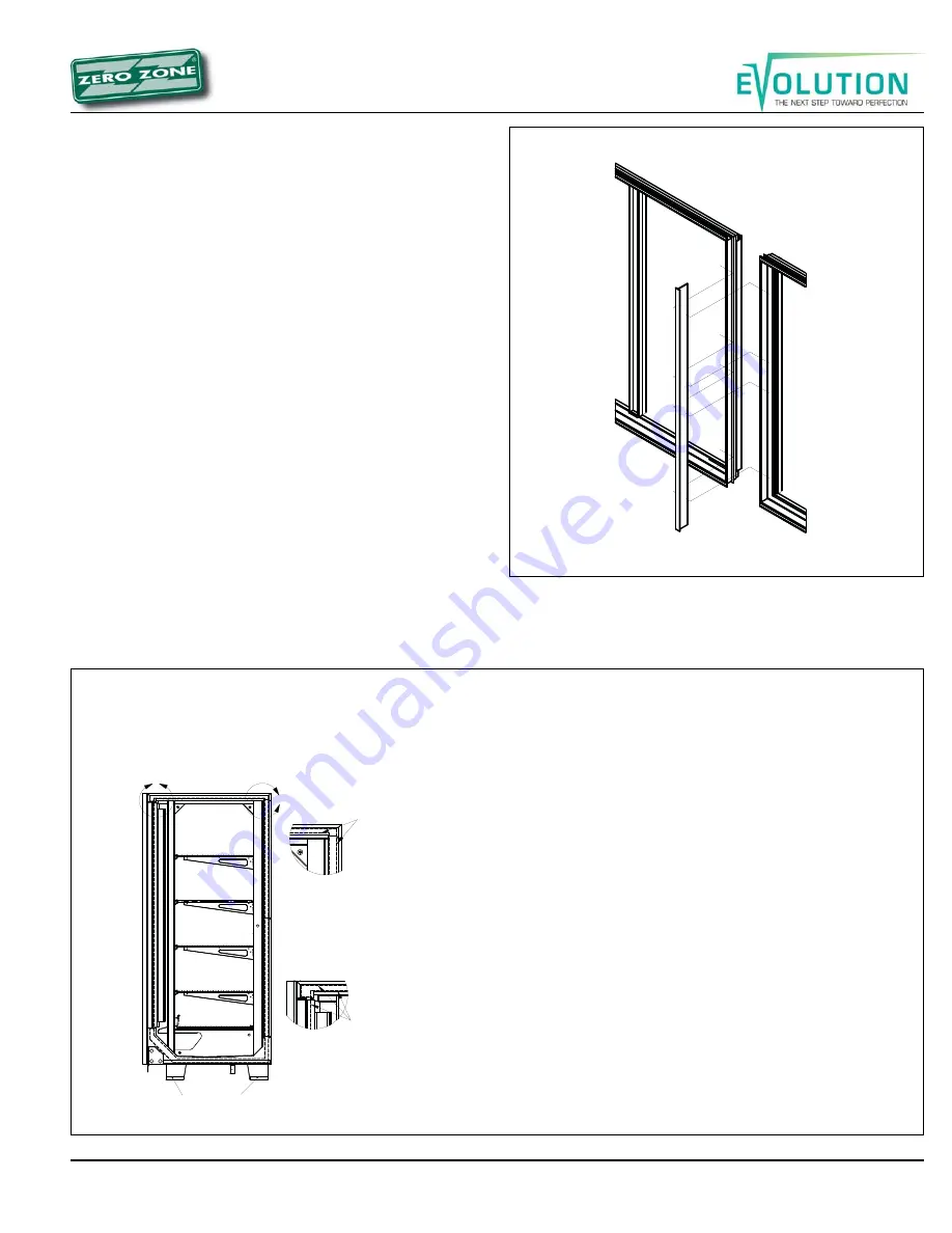
diagrams of these locations. Install tee strips between
the door frames at case joints (See Figure 10). Use the
special screws and nuts provided.
3.
Start the joining bolts, but do not tighten them. Begin
tightening the bolts at the top rear, working down the
back of the case and up the front making sure that the
front seams are flush.
4.
For NSF case installation, the interior case seams need
to be sealed using NSF approved caulk (not supplied)
(Figure 11).
5.
The end panel protector support plates should be
removed after the cases are set in their final position.
Figure 9: Caulking cases to be joined
Figure 10: T-Strips
DO NOT APPLY EXCESS AMOUNTS OF BUTYL SEALANT THAT WOULD CAUSE IT TO SQUEEZE ONTO END
FRAME METAL AREAS.
Caulk-sealant used to join cases and complete the sealing requirements for NSF compliance
should not come in contact with butyl sealant. Apply to clean, dry surfaces free of contaminants that adversely affect
adhesion and could change color of sealant joint areas over time.
Procedure for Joining Cases
These procedures are critical! Failure to follow these guide-
lines will result in a poorly functioning case. This is espe-
cially true of freezers.
1.
Apply two 1/4” to 3/8” wide beads of Butyl sealant, 1/2”
in from the inside and outside edges of foamed insu-
lated ceiling, rear wall, base and door frame to be
joined. Apply to only one case joint to avoid excessive
amounts of Butyl sealant that would squeeze out of the
joint. Sealant is not applied to the structural steel end
frames. After cases are joined, caulk the top and back
exterior seams (if possible) at this time.
2.
When joining ends of cases, caulk sealant should be
applied in the same like manner for joints.
If 4 shipping blocks are installed to inside of base ends,
remove them to comply with NSF.
A
B
DETAIL A
SCALE 1 : 5
1/4" - 3/8" TYPICAL
BUTYL SEALANT
BEADS
DETAIL B
SCALE 1 : 5
1/4" - 3/8" TYPICAL
BUTYL SEALANT
BEADS
Содержание RVZC30
Страница 1: ......
Страница 2: ...RVZC30 and BB T TBB WA RVZP30 and BB T TBB WA RVC24 2 0407...
Страница 5: ...RVZC30 and BB T TBB WA RVZP30 and BB T TBB WA RVC24 5 0407 Figure 1 Case label information...
Страница 9: ...RVZC30 and BB T TBB WA RVZP30 and BB T TBB WA RVC24 9 0407 Figure 5B All base locations...
Страница 10: ...RVZC30 and BB T TBB WA RVZP30 and BB T TBB WA RVC24 10 0407 Figure 5C All base locations...
Страница 22: ...RVZC30 and BB T TBB WA RVZP30 and BB T TBB WA RVC24 22 0407 Figure 21 Electric defrost 30 wiring...
Страница 23: ...RVZC30 and BB T TBB WA RVZP30 and BB T TBB WA RVC24 23 0407 Figure 22 Electric defrost 24 wiring...
Страница 24: ...RVZC30 and BB T TBB WA RVZP30 and BB T TBB WA RVC24 24 0407 Figure 23 Hot gas wiring...
Страница 25: ...RVZC30 and BB T TBB WA RVZP30 and BB T TBB WA RVC24 25 0407 Figure 24 Single point wiring...
Страница 26: ...RVZC30 and BB T TBB WA RVZP30 and BB T TBB WA RVC24 26 0407 Figure 25 Master satellite wiring...
Страница 29: ...RVZC30 and BB T TBB WA RVZP30 and BB T TBB WA RVC24 29 0407 Figure 27 24 Electric Figure 26 30 Electric...
Страница 30: ...RVZC30 and BB T TBB WA RVZP30 and BB T TBB WA RVC24 30 0407 Figure 28 Coil 30 Hot gas Figure 29 Coil 24 Hot gas...


