background image

12

35 mm

Min 260

Min 20

Min 180

Min 20

Min D

D

Pict. 2

Pict. 1

Installation jig,

Art. no. 51724 for Z-150/200/250

Art. no. 52312 for ZL-150/200/250

Pict. 3

4. Installation support frame

Preparation/support frame

Attention! Also refer to the truck manufacturer´s instructions for auxiliary equipment

1. Measure out and mark the centre point of the 

truck's rear frame. 

See picture 1

.

2. Fasten the jig with bolts or spot weld it to the rear 

frame so that the middle points line up. 

See picture 

2

.

3. Make the notches as required in the rear beam in 

accordance with the measures on previous pages.

4. Place the support frame of the lift under the frame 

of the truck and fit the lift arms to the installation jig. 

Use the specified platform pivot bolt.

5. Position the support frame as required under the 

truck's chassis frame (a wheeled jack is a good aid). 

See picture 3

.

The support frame ought to be positioned as high as 

possible. Note the measures on previous pages. 

The support frame must be parallel with the chassis 

frame, but it must not be pressed against the frame. 

There must be some mm between.

If it is difficult to get the support frame into its right posi

-

tion, loosen a hydraulic hose from one lift cylinder to let oil 

or air out.

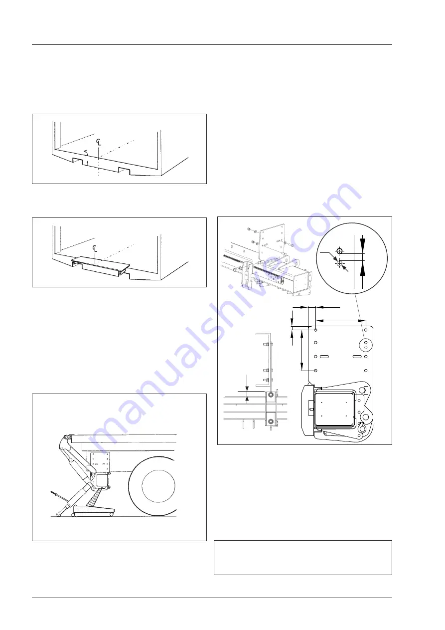
The brackets should be positioned according to picture 4. 

Slide the brackets over the support frame so that the ope-

ning points towards the front of the vehicle see picture 4. 

If adjustment is necessary, drill 

14 mm holes

 in the truck 

frame in the middle of the oval holes of the bracket. Then 

fasten the brackets securely to the frame (torque=115 Nm) 

with the delivered 

M14x45 10.9 screws

. Washers should 

be placed under the screwheads and washers under the 

nuts. 

Bag 31, 31B. See picture 4. 

NB! Welding on the mounting brackets is not allowed.

Install the u-profile end plate with the u pointing to the front 

of the vehicle using the washers and nuts provided, one 

plate for each mounting bracket, two nuts and two wash-

ers for each plate (torque=260 Nm). After testing the posi-

tion of the lift relative to  the chassis, drill the remaining 

holes in the frame on each side and fasten the brackets, 

min. 6 pcs. M14x45 10.9 115 Nm (this does not include 

screws in oval holes).

NB. Do not run the lift up against the armstops during 

installation before all the bolts between the mounting 

brackets and vehicle frame are tightened.

Note! 

Please note that the space for the bracket requires additio-

nal 35 mm between the frame of the truck and the support frame.

See pict. 4
Do not load the lift before all bolts are tightened.

Loosen the installation jig.

Pict. 4

Min 6 pcs.

M14x45 10.9 

115 Nm

New hole

Содержание Z 150-135

Страница 1: ...ephone 46 150 489550 Telefax 46 150 489551 E mail zepro zepro com Internet www zepro com Factory All v gen 4 840 73 BISPG RDEN SWEDEN Telephone 46 696 17200 Telefax 46 696 17242 E mail info zepro com...

Страница 2: ......

Страница 3: ...support frame 12 5 Electrical installtion 13 6 Electrical and hydraulic diagram 15 7 Connection unit 20 8 Installation miscellaneous 27 9 Important information 32 10 Markings positioning of decals on...

Страница 4: ...to certify conformity to the Machi nery Directive if the product is subsequently changed without his knowledge or approval In order for the product s CE marking to remain applicable the forms supplied...

Страница 5: ...when the lift is not used The lift can also be operated from other optional units To ensure safe operation even with very long control cables the hydraulic unit is equipped with relays The relays situ...

Страница 6: ...kg Mounting bracket cpl Z ZL 32 kg Liftcylinder Z ZL 150 135 8 5 kg pce Liftcylinder Z ZL 150 155 9 kg pce Liftcylinder Z ZL 150 175 10 kg pce Liftcylinder Z 150 195 13 5kg pce Liftcylinder Z ZL 200 1...

Страница 7: ...125 TP2 mm 1500 kg 610 630 650 TP2 mm 2000 kg 650 660 680 TP2 mm 2500 kg 670 680 690 C 400 C 615 TP1 mm C 800 301 246 158 TP2 mm 1500 kg 599 617 635 TP2 mm 2000 kg 629 647 665 TP2 TP1 40 C 2 General...

Страница 8: ...A 2 1 A 0 75 A 0 85 A 1 5 mm2 35 mm2 35 mm2 50 mm2 170 Ah 18 Volt 7000 2 General Max Power Consumption Pump Motor Unit Magnet hydraulic unit Magnet electric safety valve Solenoid Cable area Control c...

Страница 9: ...9 Loading Diagram 2 General...

Страница 10: ...30 872 480 907 430 937 360 972 A C 3 20 C D 800 769 765 813 715 868 665 916 615 958 565 994 515 1026 465 1054 400 1085 A C 3 20 910 890 D 40 A C 210 180 max 1710 1690 220 200 815 795 D 40 A C 210 180...

Страница 11: ...1080 665 1120 615 1150 565 1180 515 1206 450 1230 A C 3 20 1014 min 750 max 930 1432 2400 1477 1820 1246 min 982 max 1162 1664 1709 2052 2400 1000 980 D 40 A C 210 180 max 1880 1860 220 200 D 28 336 3...

Страница 12: ...to let oil or air out The brackets should be positioned according to picture 4 Slide the brackets over the support frame so that the ope ning points towards the front of the vehicle see picture 4 If...

Страница 13: ...ened together with brake pipes or other elec tric cables of the truck When passing through holes the cables must be protected with rubber bushings A 160 A 24 V or 250 A 12 V fuse is to be installed on...

Страница 14: ...f cables is done with similar care to avoid damage from contact with edges of the frame and other parts of the vehicle This will increase the life of the cables and reduce the risk of unnecessary down...

Страница 15: ...Stock nr Ritningsnr Drawing nr Blad Sheet Format Size Revision F r denna ritning g ller IS0 toleranser SMS ritregler Toleranser Tolerance Ytj mnhet Surface finish Svets Welding 1 1 Ritad Drawn A HIAB...

Страница 16: ...16 Z ZL 150 200 250 DA 6 Electric and hydraulic diagram...

Страница 17: ...r Blad Sheet Format Size Revision F r denna ritning g ller IS0 toleranser SMS ritregler Toleranser Tolerance Ytj mnhet Surface finish Svets Welding 1 1 Ritad Drawn A HIAB brand part of Cargotec Corpor...

Страница 18: ...the trailer body exterior represents the alarm indica tion clearly visible so that the driver can see it in the mirror The light must be of amber color Connect the lamp indicator according to the ele...

Страница 19: ...19 6 Electric and hydraulic diagram 3 button control unit with main switch and selector switch 3 button remote control unit with spiral cable 3 button control unit 4 button control unit...

Страница 20: ...splay Program configuration The flashing light indicates Supply voltage Off No supply voltage On Supply voltage available but CS cabin switch is not active Flashing CS cabin switch is active the syste...

Страница 21: ...ed by the figures 1 7 1 Fixed control device 1 including two hand button 2h1 2 Fixed control device 2 including two hand button 2h2 3 Radio control device External 4 Coil control device 5 Truck slider...

Страница 22: ...for This primarily applies to radio and coil con trol devices as other control devices have such a short locking period that there is no time to see the indication The number will stop flashing when...

Страница 23: ...h a list containing the five latest faults detected before the display goes off Fault codes Identification Code 1 Code 2 Code 3 Information Other L Low battery voltage 07 35 Voltage measured H High ba...

Страница 24: ...codes Output No 3 short circuited Supply voltage A supply voltage of between 8 0V and 15 0V is regarded by the unit as correct for a 12V system A supply voltage of between 18 0V and 29 0V is regarded...

Страница 25: ...ure connected to tilt cylinders side sends when activated signal back to Di5 which blocks cancels lift and tilt up functions No signal in on Cs results in blocked control unit con nectors Signal to Cs...

Страница 26: ...ANKL DA CHASSIS WITH TANK LTANK TANKLOCK FILLER CAP TANKDECKEL VENTILHUS VALVE BODY VENTIL GEHAUSE MOTOR SOLENOID SWITCH MAGNETSCHELTER S U1 U3 U2 KRETSKORT CIRCUIT CARD GETRUCTE SCHALTUNG KOPPLINGSEN...

Страница 27: ...adjusted to 4 different height positions pict 6 The outer brackets can be adjusted to 5 different horizontal positions pict 6 1 The lateral distance between bumper bar and moving parts of the tail lif...

Страница 28: ...he top of the platform Steel Pict 12 Pict 11 Pict 10 Installation of platform Install platform onto the lift arms and tilt cylinders to the platform Use axles and support wheels provided 280 Nm pict 1...

Страница 29: ...hence hydraulically locked under transport 8 Installation continued Pict 14 Armstops Install armstops for both arms at the rear beam Install them equal on both sides so they meet the liftarms at the...

Страница 30: ...y the right cylinder and then left one so that the platform fits exactly to the body as per pict B NB Always adjust right and left sides the same 4 In order to ensure that the lock nut and collar re m...

Страница 31: ...p against the body Run the lift up so that the lift is at the floor level see pict 20 Loosen the ring s lock screw 2 Screw the ring out in the direction of the platform 3 See pict 21 Tilt down the pla...

Страница 32: ...en the final post installation testing is carried out it is important that there is sufficient clearance between the cylinders working envelopes and all fixed points During lift operation and cylinder...

Страница 33: ...clearly indicates the nominal loading and the diagram shows the maximum permitted loading at different positions on the platform The name plate is installed on the support frame of the tail lift and...

Страница 34: ...34 10 Markings decals...

Страница 35: ...ylinder lower bearing 6 Liftarm left side lower bearing 7 Lift tiltcylinder upper bearing 8 Right tiltcylinder upper bearing 9 Liftarm right side upper bearing 10 Right liftcylinder upper bearing 11 L...

Страница 36: ...Place a test load on the platform according to the table for the corresponding tail lift model and loading capacity The tail lift should be in the same level and angle as floor Leave the test load on...

Страница 37: ...overflow valve is activated when the lift is run up to the floor level or armstops That the tail lift cannot be lowered or tilted down respectively if the electrical connector from the lift and tilt...

Страница 38: ...tilt cylinder s lower axle at the sup port frame Remove the cylinder and take away the hoses NB Oil can leak from the hoses and cylinder 6 Dismantle the side profiles from the platform Take away the...

Отзывы: