3-8
3. SERVO CIRCUIT
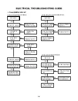
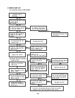
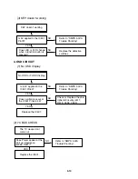
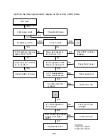
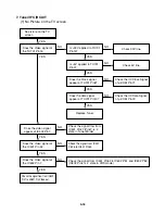
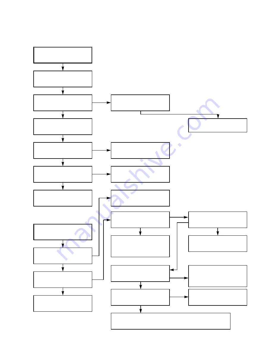
(1) Unstable Video in PB MODE
Unstable Video in
PB Mode.
Does the Noise level of the
screen change
periodically?
Do the CTL pulses appear
at the IC501 Pin97?
Is adjusting the height of
the CTL Head accurate?
Readjust the height of the
CTL Head.
Replace the IC501.
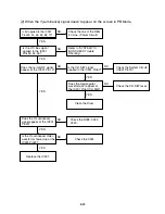
Refer to “When the Y signal
doesn’t appear on the
screen in PB Mode”.
Does the CFG waveform
appear at the IC501
Pin87?
On tracking do the CTL
pulses move?
Does the Video Envelope
waveform appear at the
IC501 Pin9?
Replace the IC501.
YES
YES
YES
YES
YES
YES
NO
NO
NO
NO
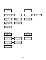
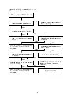
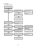
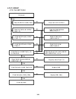
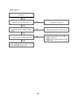
(2) When the Drum Motor
(2)
doesn’t run.
Do the DFG Pulses appear
at the PMC01 Pin11?
Replace the Cap M.
Aren’t the foil patterns and
the Components between
IC501 Pin 90 and PMC01
Pin11 short?
Replace the IC501.
Refer to “(2)
No 12VA of Power section”
Do the Drum PWM Pulses
appear at the IC501
Pin76?
Aren’t the foil patterns and
the Components between
IC501 Pin76 and PMC01
Pin12 short?
Do the DFG Pulses appear
at the IC501 Pin90?
Do the Drum PWM Pulses
appear at the IC501
Pin76?
Aren’t the connecting patterns and the Components
between IC501 Pin76 and PMC01 Pin12 short?
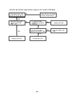
When the Drum Motor
doesn’t run,
Does 12V appear at the
PMC01 Pin8?
Does 2.8V appear at the
PMC01 Pin12?
Check the connector
(PMC01) and the Drum
Motor Ass’y.
NO
YES
YES
YES
NO
NO
NO
NO
NO
YES
YES
YES
Содержание ABV341 Series
Страница 2: ......
Страница 36: ...3 34 3 35 2 TU IF CIRCUIT DIAGRAM PB REC...
Страница 39: ...3 40 3 41 5 JACK CIRCUIT DIAGRAM...
Страница 41: ...3 44 3 45 7 TIMER CIRCUIT DIAGRAM XBV343...
Страница 42: ...3 46 3 47 8 TIMER CIRCUIT DIAGRAM XBV342...
Страница 45: ...3 52 3 53 PRINTED CIRCUIT DIAGRAMS 1 MAIN P C BOARD LOCATION GUIDE...
Страница 65: ...02 12 04 R17149A ZENITH DAP202K 3 80 3 81 6 JACK CIRCUIT DIAGRAM...
Страница 70: ...LOCATION GUIDE 3 90 3 91 PRINTED CIRCUIT DIAGRAMS 1 MAIN P C BOARD TOP VIEW...
Страница 71: ...LOCATION GUIDE 3 92 3 93 2 MAIN P C BOARD BOTTOM VIEW...
Страница 92: ...3 114 2 Audio related Signal ASDAT3 IC501 PIN 157 ABCK IC501 PIN 148 ALRCK IC501 PIN 149 ASDATA3 FIG 14 2...
Страница 98: ...3 121 3 122 2 RF DSP SERVO CIRCUIT DIAGRAM CD DVD LD will not on COMBI SCART MTK 03 3 25 SR17445A...
Страница 99: ...3 123 3 124 3 AUDIO CIRCUIT DIAGRAM COMBI SCART MTK 03 3 25 SR17447A...
Страница 100: ...3 125 3 126 4 AV JACK CIRCUIT DIAGRAM COMBI SCART MTK 03 3 25 SR17446A...
Страница 103: ...3 131 3 132 PRINTED CIRCUIT DIAGRAMS 1 MAIN P C BOARD LOCATION GUIDE...
Страница 110: ...EXPLODED VIEW 1 Deck Mechanism Exploded View 5 1 CONTENTS SECTION 5 MECHANISM OF DVD PART MTK MODEL...
Страница 134: ...4 22 GEAR F R GEAR AY P2 P3 F R Lever Tension Base Boss CAM...

