4-16
DECK MECHANISM ADJUSTMENT
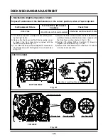
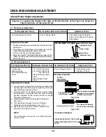
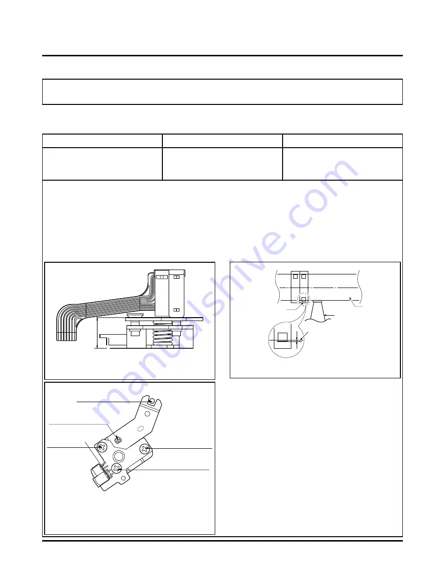
5. Audio/Control (A/C) Head Adjustment
10.9
Purpose: To insure that the Tape passes accurately over the Audio and Control Tracks in
exact alignment in both the Record and Playback Modes.
Test Equipment/ Fixture
• Blank Tape
• Screw Driver (+) Type 5mm
• Play the blank tape
Test Conditions (Mechanism Condition)
Adjustment Point
• Tilt Adjustment Screw (C)
• Height Adjustment Screw (B)
• Azimuth Adjustment Screw (A)
Fig. C-5-1
A/C Head Base
Fig. C-5-2
Height Adjustment
Screw (B)
Tilt Adjustment
Screw (C)
Azimuth Adjustment
Screw (A)
X-Value Adjustment
Hole
Fixed Screw
Fig. C-5-3
A/C Head
Tape
Tape
0.2~0.25mm
P4
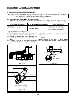
5-1. Preliminary Adjustment (Height and Tilt Adjustment)
Perform the Preliminary Adjustment, when there is no Audio Output Signal with the Alignment Tape.
1) Adjust the A/C Head Base Assembly as shown Fig. C-5-
1 by using the Height Adjustment Screw (B).
2) Play a Blank Tape and observe if the Tape passes accu-
rately over the A/C Head without the Tape Curling or
Folding.
3) If Folding or Curling occurs adjust the Tilt Adjustment
Screw (C) while the Tape is running to resemble Fig. C-
5-3.
4) Reconfirm the Tape Path after playback of approximate-
ly 4~5 seconds.
Ideal A/C head height occurs when the tape runs between
0.2~0.25mm above the bottom edge of the A/C head core.
NOTE
Adjustment Procedure/Diagrams
A/C Head Assembly
Содержание ABV341 Series
Страница 2: ......
Страница 36: ...3 34 3 35 2 TU IF CIRCUIT DIAGRAM PB REC...
Страница 39: ...3 40 3 41 5 JACK CIRCUIT DIAGRAM...
Страница 41: ...3 44 3 45 7 TIMER CIRCUIT DIAGRAM XBV343...
Страница 42: ...3 46 3 47 8 TIMER CIRCUIT DIAGRAM XBV342...
Страница 45: ...3 52 3 53 PRINTED CIRCUIT DIAGRAMS 1 MAIN P C BOARD LOCATION GUIDE...
Страница 65: ...02 12 04 R17149A ZENITH DAP202K 3 80 3 81 6 JACK CIRCUIT DIAGRAM...
Страница 70: ...LOCATION GUIDE 3 90 3 91 PRINTED CIRCUIT DIAGRAMS 1 MAIN P C BOARD TOP VIEW...
Страница 71: ...LOCATION GUIDE 3 92 3 93 2 MAIN P C BOARD BOTTOM VIEW...
Страница 92: ...3 114 2 Audio related Signal ASDAT3 IC501 PIN 157 ABCK IC501 PIN 148 ALRCK IC501 PIN 149 ASDATA3 FIG 14 2...
Страница 98: ...3 121 3 122 2 RF DSP SERVO CIRCUIT DIAGRAM CD DVD LD will not on COMBI SCART MTK 03 3 25 SR17445A...
Страница 99: ...3 123 3 124 3 AUDIO CIRCUIT DIAGRAM COMBI SCART MTK 03 3 25 SR17447A...
Страница 100: ...3 125 3 126 4 AV JACK CIRCUIT DIAGRAM COMBI SCART MTK 03 3 25 SR17446A...
Страница 103: ...3 131 3 132 PRINTED CIRCUIT DIAGRAMS 1 MAIN P C BOARD LOCATION GUIDE...
Страница 110: ...EXPLODED VIEW 1 Deck Mechanism Exploded View 5 1 CONTENTS SECTION 5 MECHANISM OF DVD PART MTK MODEL...
Страница 134: ...4 22 GEAR F R GEAR AY P2 P3 F R Lever Tension Base Boss CAM...


