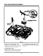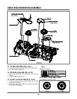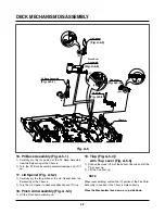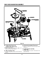
4-14
DECK MECHANISM ADJUSTMENT
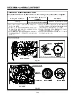
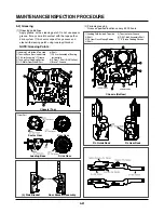
Purpose: To insure smooth Transport of the Tape during each Mode of Operation.
If the Tape Transport is abnormal, then check the Torque as indicated by the chart below.
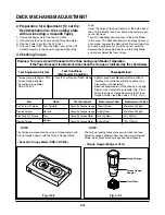
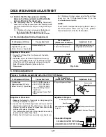
2. Preparation for Adjustment (To set the
Deck Mechanism to the Loading state
without inserting a Cassette Tape).
1) Unplug the Power Cord from the AC Outlet.
2) Disassemble the Top Cover and Top Plate Assembly.
3) Plug the Power Cord into the AC Outlet.
4) Turn the Power S/W. Push the Stop Lever of the CST
Holder Assembly to the back for Loading without the
Tape.
Cover the Holes of the End Sensors at the both sides of
the (L) Side Bracket and Door Bracket Assembly to pre-
vent a light leak.
Then The Deck Mechanism drives to the Stop Mode.
In this case, The Deck Mechanism can accept inputs of
each mode, however the Rewind and Review Operation
can not be performed for more than a few seconds
because the Take-up Reel Table is in the Stop Mode
and can not detect the Reel Pulses.
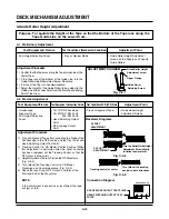
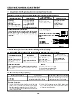
3. Checking Torque
The Values are measured by using a Torque Gauge and
Torque Gauge Adaptor with the Torque Gauge affixed.
The Torque reading to measure occurs when the Tape
abruptly changes direction from Fast Forward of Rewind
Mode, when quick bracking is applied to both Reels.
SRK
VIDEO
CASSETTE
TORQUE
METER
VHT-303
S
R
K
-
V
H T
- S
SR
K - V H T - T
300
250
200
150
50
0
300
250
200
150
50
0
100
Test Equipment/ Fixture
• Torque Gauge (600g/cm ATG)
• Torque Gauge Adaptor
• Cassette Torque Meter
SRK-VHT-303
Checking Method
• Perform each Deck Mechanism Mode without
inserting a Cassette Tape (Refer to above No.2
Preparation for Adjustment).
• Read the Measurement of the Take-up or Supply
Reels on the Cassette Torque Meter (Fig. C-3-2).
• Attach the Torque Gauge Adaptor to the Torque
Gauge and then read the Value of it (Fig. C-3-1).
NOTE:
Fig. C-3-2
Fig. C-3-1
Torque Gauge
Torque Gauge
Adaptor
Reel Table
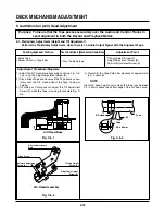
Item
Fast Forward Torque
Rewind Torque
Play Take-Up Torque
Review Torque
Mode
Fast Forward
Rewind
Play
Review
Test Equipment
Cassette Torque Gauge
Cassette Torque Gauge
Cassette Torque Meter
Cassette Torque Meter
Measurement Reel
Take-Up Reel
Supply Reel
Take-Up Reel
Supply Reel
Measurement Values
More than 400g/cm
More than 400g/cm
40~100g/cm
120~210g/cm
Test Conditions
(Mechanism Condition)
• Play (FF) or Review (REW) Mode
NOTE:
• Cassette Torque Meter (SRK-VHT-303)
• Torque Gauge (600g.cm ATG)
Содержание ABV341 Series
Страница 2: ......
Страница 36: ...3 34 3 35 2 TU IF CIRCUIT DIAGRAM PB REC...
Страница 39: ...3 40 3 41 5 JACK CIRCUIT DIAGRAM...
Страница 41: ...3 44 3 45 7 TIMER CIRCUIT DIAGRAM XBV343...
Страница 42: ...3 46 3 47 8 TIMER CIRCUIT DIAGRAM XBV342...
Страница 45: ...3 52 3 53 PRINTED CIRCUIT DIAGRAMS 1 MAIN P C BOARD LOCATION GUIDE...
Страница 65: ...02 12 04 R17149A ZENITH DAP202K 3 80 3 81 6 JACK CIRCUIT DIAGRAM...
Страница 70: ...LOCATION GUIDE 3 90 3 91 PRINTED CIRCUIT DIAGRAMS 1 MAIN P C BOARD TOP VIEW...
Страница 71: ...LOCATION GUIDE 3 92 3 93 2 MAIN P C BOARD BOTTOM VIEW...
Страница 92: ...3 114 2 Audio related Signal ASDAT3 IC501 PIN 157 ABCK IC501 PIN 148 ALRCK IC501 PIN 149 ASDATA3 FIG 14 2...
Страница 98: ...3 121 3 122 2 RF DSP SERVO CIRCUIT DIAGRAM CD DVD LD will not on COMBI SCART MTK 03 3 25 SR17445A...
Страница 99: ...3 123 3 124 3 AUDIO CIRCUIT DIAGRAM COMBI SCART MTK 03 3 25 SR17447A...
Страница 100: ...3 125 3 126 4 AV JACK CIRCUIT DIAGRAM COMBI SCART MTK 03 3 25 SR17446A...
Страница 103: ...3 131 3 132 PRINTED CIRCUIT DIAGRAMS 1 MAIN P C BOARD LOCATION GUIDE...
Страница 110: ...EXPLODED VIEW 1 Deck Mechanism Exploded View 5 1 CONTENTS SECTION 5 MECHANISM OF DVD PART MTK MODEL...
Страница 134: ...4 22 GEAR F R GEAR AY P2 P3 F R Lever Tension Base Boss CAM...

