ZENA mobile welding system -- Operators Manual -- Series 150 & 200 Welders
16
16
will be either idle speed or welding speed. For example,
before
the power
control on the welding handle is depressed the built-in tachometer circuit will be
reading idle speed.
1.2
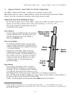
Start the engine, allow it to warm up, then observe SCM.V2 Lamps 2-4.
NOTE1: Depending on engine temperature and whether, or not, the engine has
idled for an extended period, normal idle speed will vary between 2,500
to 3,500 rpm
8
. Idle speed may acceptably fall anywhere within this
range.
NOTE2: The speed control module will automatically try to increase idle speed
whenever it determines that the idle speed is too low.
At this point, Tachometer Lamps 2 through 4 should be cycling from green to
red and/or green to yellow. You will not likely see Lamp 3 (green) illuminated
continuously. Periodic flashing -- alternating with one of the other tachometer
indicator lamps is the typical mode of operation. Likewise, you should not see
Lamp 2 (yellow) remaining on steadily, for more than a second or two -- nor
should Lamp 4 (red) remain on for more than 20 seconds.
Lamp 5 (yellow)
9
should also be on (flashing rapidly) at this point. Lamp 1
(green)
10
and Lamp 6 (red)
11
should be off.
If all lamps are working normally, go to the next step.
If Lamps 2-5 are not illuminated, and if Lamp 6 is flashing slowly tachometer
signals from the engine are missing, or the SCM.V2 module may be defective.
Goto Step 1.4.
If none of the lamps are illuminated, power is not getting to the module, the
module’s built in computer may not have started properly, or the module may
be defective. Stop and restart the engine. Recheck the lamps. If they are all
still off, goto Step ??.
If Lamp 5 (yellow) is flashing rapidly), Lamp 1 (green) and Lamp 6 (red) are
off, but none of the Tachometer Lamps 2-4 are illuminated, the module’s built
in computer may not have started properly, or the SCM.V2 module may be
defective. Stop and restart the engine. Recheck the lamps. If Lamps 2-4 are
still not illuminated, goto Step ??.
If Lamp 5 (yellow) is flashing rapidly), Lamp 1 (green) and Lamp 6 (red) are
off, but the Tachometer Lamps 2-4 are not indicating correct idle speed,
carburetor adjustment is indicated. Go to page ?? follow the carburetor
adjustment procedure, and retest the system.
1.3
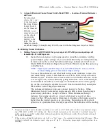
We will now determine if the engine speed is correct
12
prior
to starting a
welding arc
13
. This test checks both the function of the SCM.V2 module and
the throttle control actuator mechanisms.
8
The automatic engine speed control module works to maintain a proper idle speed regardless of engine
temperature. It is not unusual to see a higher RPM for a short period of time just after welding has been
completed -- with a lower rpm normal with a cold engine, or one which has been idling for a period of time.
9
Lamp 5 indicates the presence of a tachometer signal from the engine. During normal engine operation it will
always have a flickering glow -- with the speed of the “flicker” following the speed of the engine (at high speeds
the flicker is so fast that the light will, at first, seem steady.
10
Lamp 1 should illuminate whenever the Power Control Button on the electrode holder is depressed and it should
remain on until the Button is released.
11
Lamp 6 should illuminate (with a steady glow, not flashing) whenever engine speed is greater than 5500 rpm.
Содержание 150 series
Страница 2: ......
Страница 5: ......
Страница 6: ......
Страница 12: ...ZENA mobile welding system Operators Manual Series 150 200 Welders 6 6 This page intentionally left blank...
Страница 35: ...ZENA mobile welding system Operators Manual Series 150 200 Welders 29 29 This page intentionally left blank...
Страница 37: ...ZENA mobile welding system Operators Manual Series 150 200 Welders 31 31 This page intentionally left blank...


