ZENA mobile welding system -- Operators Manual -- Series 150 & 200 Welders
19
19
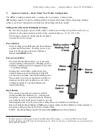
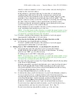
Handle. Lamp #2 (
and
Lamp #3 for a “RO” type Module) should light and
remain lit for as long as the Power Button is held down. You should also hear a
very faint “clicking” sound coming from the Control Module. If Lamp #2 (and
Lamp #3) is working properly, and if you
are
hearing the faint clicking sound,
go on to the next step.
If Lamp #2
is
not
working properly, AND if you
are
hearing the faint clicking
sound, the Control Module is malfunctioning. Go to step 2.9.
If you have a type “RO” Module, and if Lamp #2
is
not
working properly BUT
Lamp #3
is
working properly, AND if you
are
hearing the faint clicking sound
you have a “blown” 10A fuse -- and/or a defective Control Module. Go to Step
2.10.
If Lamp #2
is
not
working properly, AND if you
are
not
hearing the clicking
sound, go to step 2.10.
If you have a type “RO” Module, and if Lamp #2
is
not
working properly BUT
Lamp #3
is
working properly, AND if you
are not
hearing the faint clicking
sound, go to Step 2.11.
2.7
Check to insure that the Gray wires which connect the Power Control Module to
the Welding Power Generator are properly connected to the Power Generator,
that the connectors at the ends of the Gray wires are secure, and that the gray
wires have not been damaged. Also insure that the Yellow wire (not used in
most basic welder installations) is not short circuiting to chassis ground or to any
other component. Also check and insure that the Yellow wire is not connected
to anything other than to another Yellow wire from either a ZENA WC.12S
Slave Control Module or a ZENA WC.VR Universal Voltage/Current
Regulator. If any wires were not properly connected, correct the problem and
go to step 2.8. If the wires were properly connected, it is likely that you have a
problem within your Power Generator, go to step 2.12.
2.8
Congratulations, it is likely that you have successfully corrected your problem.
Fully re-test your welding system to make sure.
2.9
You have a problem which requires the assistance of our tech support
department (877-ZENA INC or 615-897-2011).
2.10 It is possible that an internal fuse has been “blown”.
The Control Module’s internal solder-in fuses are covered with a silicone
adhesive/sealant. Carefully remove the silicone to expose the fuse leads.
Using a test lamp or a volt meter with a sharp test probe, check for the presence
of power (12 volts or 24 volts) at the end of the 10 amp. fuse which is
farthest
from the point where wires enter/exit the Control Module. The 10 amp. fuse
(one of two internal fuses in the Control Module) is the “bottom” or lower fuse
when viewing the Control Module from above, with the wires from the Control
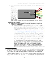
Module on the viewer’s left. (SEE CONTROL MODULE DIAGRAM ON
PREVIOUS PAGE) If you do not have a test lamp or meter, go to step 2.9.
If power
is
present at the end of the fuse, it is likely that the Power Control
Module is defective. Go to step 2.9.
If power
is
not
present at the end of the 10 amp. fuse, you have a “blown” fuse.
A 10A fuse failure may indicate a possible failure in the Control Module itself,
but more likely it is pointing to a component failure in the Power Generator, OR
Содержание 150 series
Страница 2: ......
Страница 5: ......
Страница 6: ......
Страница 12: ...ZENA mobile welding system Operators Manual Series 150 200 Welders 6 6 This page intentionally left blank...
Страница 35: ...ZENA mobile welding system Operators Manual Series 150 200 Welders 29 29 This page intentionally left blank...
Страница 37: ...ZENA mobile welding system Operators Manual Series 150 200 Welders 31 31 This page intentionally left blank...


