ZENA mobile welding system -- Operators Manual -- Series 150 & 200 Welders
21
21
than 1.4 ohms
, your Power Generator has a component failure, and must be
returned for repair. Go to Step 2.9.
If the electrical resistance measured between the control terminals is
higher
than the “normal” range of 1.4 to 2.4 ohms
(for example, 10 ohms or 20
ohms or more) it is an indication of grease or some similar material which has
caused “fouling” coating of the brushes and or internal slip-rings. Cleaning can
be accomplished in the field, if necessary, but is best done under factory
conditions. Such cleaning, will be performed free of any labor charge, with
charges only for return freight cost. Go to Step 2.9.
If your electrical resistance between the control terminals is correct, you should
also measure the electrical resistance between either of the terminal and the
case of the Power Generator. A normal reading is an “open” circuit (an infinite
resistance). If your meter shows any measurable resistance, your Power
Generator has a component failure, and must be returned for repair. Go to Step
2.9.
If all resistance readings at the control terminals were found to be “normal”,
reconnect all wires, and go on to the next step.
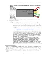
2.13 Attach a DC voltmeter between the electrode holder clamp and the ground
clamp. Set the power control dial to its full CW position (max. power setting).
Then, with the engine running, and with power “on” to the welding system,
depress the power button on the electrode holder and note the voltage reading.
If the voltage is significantly lower than 60VDC, or above 80VDC, it is likely
that you have a component failure in the high current section of the welding
power generator and it should be returned for repair. (NOTE: If, for some
reason, this is not possible, field replacement of defective components can be
accomplished by a skilled technician.) Go to Step 2.9.
If the voltage is between 60 and 80VDC, your system is likely developing full
welding power and you should be strike an arc an begin welding. However, go
to step 2.14 for one final check.
2.14 With your DC voltmeter still connected between the electrode holder clamp and
the ground clamp. Depress the power button on the electrode holder and note
the voltage reading while you rotate the power control dial to its full CCW
position. You should note that the voltage
decreases
as the control dial is
rotated. If this voltage does not decrease, it is likely that you have a component
failure in the high current section of the welding power generator, and it should
be returned for repair. (NOTE: If, for some reason, this is not possible, field
replacement of defective components can be accomplished by a skilled
technician.) Go to Step 2.9.
3. Welding
Power
is
Available
BUT
is
Not
Adjustable -- Control Models
WC.12 & WC.24
3.1
With the engine OFF, open the Control Module and observe Lamp #2 while
holding the Control Handle Power Button “down” and rotating the Power
Control Dial on the Control Handle.
If Lamp #2 changes in intensity, your problem is either in the Power Generator
or the Control Module. Go to step 3.2.
3.2
You can easily check for a component failure in the Power Generator by
disconnecting the two Gray wires which are used to connect the Control Module
to the Power Generator’s control terminals, and check in the electrical
Содержание 150 series
Страница 2: ......
Страница 5: ......
Страница 6: ......
Страница 12: ...ZENA mobile welding system Operators Manual Series 150 200 Welders 6 6 This page intentionally left blank...
Страница 35: ...ZENA mobile welding system Operators Manual Series 150 200 Welders 29 29 This page intentionally left blank...
Страница 37: ...ZENA mobile welding system Operators Manual Series 150 200 Welders 31 31 This page intentionally left blank...


