background image

   EN

   17

6.1   For replacing filters

The replacement period of the filter depends on 
local circumstances. We recommend replacing the 
filter when replacing the ComfoAir Luxe filter.

 Replace the filter (at least) once every six 
months.

1.   Disconnect the ComfoAir Luxe from its power 

supply.

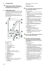
2.   Remove the filter handle (A) from the 

Comfofond-L.

A


A

Comfofond-L 350   

Comfofond-L 550

3.   Remove the old filter (B) from the Comfofond-L.
 

%

$

$

(

$

$

)

4.   Slide the new filter back into the Comfofond-L.
5.   Click the filter handle (A) in the Comfofond-L.
6.   Return power to the ComfoAir Luxe.

 Filters must be replaced with the original 
manufacturer’s filters only.

6.2   Cleaning condensation drain

 Inspect the Comfofond-L condensation 
drain at least once a year.

1.   Disconnect the ComfoAir Luxe from its power 

supply.

2.   Disconnect the condensation drain.
3.   Perform the following checks of the 

condensation drain siphon:


•   Check whether the drain is still open by 

adding extra water to the siphon.


•   Visually inspect the condensation drain for 

contamination.


•   Check that there is enough water in the 

siphon. Air may not pass through the siphon.

4.   Resolve any established problems.
5.   Reconnect the condensation drain.
6.   Return power to the ComfoAir Luxe.

6.3   Inspecting brine loop

 Inspect the brine loop at least once a year.

Check the system pressure on the pressure meter. 
Top up the system if required.

 The brine loop pressure must be between 
0.5 and 2.5 bar for the system to operate 
well. The ideal pressure is 1.5 bar.

Filling instructions:

Only a recognized cooling-technology fitter 
may top up the Comfofond-L.

Top up the system as follows:
1.   Disconnect the ComfoAir Luxe from its power 

supply.

2.   Remove the filter handle from the Comfofond-L.
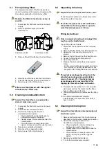
3.   Release the front panel by removing the 6 

screws.

4.   Remove the front panel from the Comfofond-L.
5.   Connect a filling hose to filling valve V3.
6.   Open filling valve V3.
7.   Measure the glycol percentage using a glycol 

meter.

     -  Fill the system with a ready-made fluid mixture 

first if required. The filling instructions for this 
are given in the "Filling the brine loop" section.

 The glycol percentage deviation from the 
selected percentage during installation 
may not exceed -3%. The desired glycol 
percentage must be restored first after 
topping up the system twice with water. 

8.   Pre-pressurise the system to 1.5 bar using the 

water pressure from the mains. Use the filling 
hose on filling valve V3 for this.

9.    Closing filling valve V3 and disconnect the filling 

hose.

10.  If no further maintenance is required:
 

Install all parts in reverse order. (from point 4 
back to point 1)

6.4   Cleaning internal siphon

 Inspect the Comfofond-L internal siphon at 
least once a year.

1.   Remove the front panel of the Comfofond-L as 

described in the brine loop maintenance section.

2.   Perform the following checks of the 

Comfofond-L internal siphon:


•    Check whether the drain is still open by  

adding extra water to the siphon. 


•    Visually inspect the condensation drain for  

contamination.


•    Check that there is enough water in the 

siphon. Air may not pass through the  
siphon.

3.   Resolve any established problems.
4.   If no further maintenance is required:  

Содержание ComfoFond-L

Страница 1: ...Installation manual Installatie handleiding Installation Anleitung Manuel de l installateur Manuale per l installatore Instrukcja obs ugi Comfofond L comfosystems...

Страница 2: ...II All rights reserved This documentation has been compiled with the utmost care The publisher cannot be held liable for any damage caused as a result of missing or incorrect information in this manu...

Страница 3: ...loop terrestrial heat collector 10 4 5 Electrical connections 11 5 Commissioning 12 5 1 Filling the brine loop 12 5 2 Adjusting the fluid pump 13 5 3 Registering the Comfofond L on the ComfoAir Luxe 1...

Страница 4: ...ne loop dimensions 20 8 2 Fluid mixture 21 8 3 Fluid pump settings 21 8 4 Air resistance 21 8 5 Cooling capacity 22 8 6 Heating capacity 22 8 7 Service parts 23 9 CE certification and warranty 24 I In...

Страница 5: ...g pictograms are used in this manual Point to watch Risk of damage to the device performance of the unit is compromised if instructions are not observed carefully Risk of personal injury for the user...

Страница 6: ...is manual Personal injury or damage to the Comfofond L can arise from non compliance with the safety regulations warnings comments and instructions in this manual The Comfofond L may only be fitted co...

Страница 7: ...llation conditions and dimensional sketches In order to determine whether the Comfofond L can be installed in a certain area the following aspects must be taken into account The Comfofond L must be in...

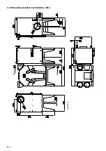
Страница 8: ...EN 4 3 1 Dimensional sketch Comfofond L 350 L Elevation P...

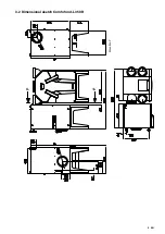
Страница 9: ...EN 5 3 2 Dimensional sketch Comfofond L 350 R Elevation P...

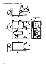
Страница 10: ...EN 6 3 3 Dimensional sketch Comfofond L 550 L Elevation P...

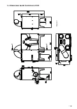
Страница 11: ...EN 7 3 4 Dimensional sketch Comfofond L 550 R Elevation P...

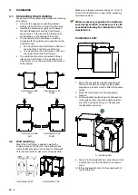
Страница 12: ...air Comfofond L 550 Comfofond L 550 Left Right 4 2 Wall mounting Mount the Comfofond L against a wall with a minimum mass of 200 kg m2 The Zehnder base frame optional extra must be used for other wal...

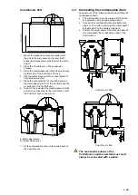
Страница 13: ...r connections on the Comfofond L and the ComfoAir Luxe vapour proof A A Metal sleeve joint B Plastic sleeve joint 7 Fit the condensation drain to the underneath of the Comfofond L 4 3 Connecting the c...

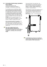
Страница 14: ...actual length for the calculation is the length that is physically in the ground The length inside the house has no further effect on the energy that the system can extract The required pipe length fo...

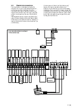
Страница 15: ...fed by the ComfoAir Luxe To do so the temperature sensor and fluid pump of the Comfofond L must be connected to the Luxe connection printed circuit board on the ComfoAir Luxe This Luxe connection pri...

Страница 16: ...removing the 6 screws 6 Remove the front panel from the Comfofond L 7 Set the fluid pump to the highest setting by turning the switch on the pump to setting 7 8 Connect a filling hose with external fi...

Страница 17: ...l which can be used to note the setting used 5 3 Registering the Comfofond L on the ComfoAir Luxe The control for the Comfofond L is not activated as standard on the ComfoAir Luxe This must be registe...

Страница 18: ...3 of the ComfoAir Luxe In the Winter mode the ComfoAir Luxe will switch around the temperature that is set in P menu P62 The best setting for P menu P62 is a few degrees below the lowest fluid tempera...

Страница 19: ...perature 8 Press OK MENU P60 will be displayed on the screen 9 Press OK MENU 2 times Current ventilation setting will be displayed on the screen Setting temperature via CC Ease 1 Press and together fo...

Страница 20: ...To ensure a hassle free lifespan for your Comfofond L we recommend you take out a service agreement with an expert company The following maintenance may be carried out by the user Replacing the filte...

Страница 21: ...ure is 1 5 bar Filling instructions Only a recognized cooling technology fitter may top up the Comfofond L Top up the system as follows 1 Disconnect the ComfoAir Luxe from its power supply 2 Remove th...

Страница 22: ...valve V3 slowly until the system is depressurised 5 Replace the fluid pump 6 Top up the system to the nominal pressure of 1 5 bar in accordance with the filling instructions in the brine loop maintena...

Страница 23: ...h the power supply to the ComfoAir Luxe back on as described in the maintenance section for the brine loop 6 11 Replacing de aerator 1 Remove the front panel of the Comfofond L as described in the bri...

Страница 24: ...nect the siphon Condensation leak Condensation drain clogged Clean both condensation drains at the top and bottom of the Comfofond L Condensation on the pipes and or fluid and air connections Insulate...

Страница 25: ...1800 W 2500 W Cooling capacity 2000 W 3000 W Maximum sound capacity 40 dB A 40 dB A Ideal fluid pressure 1 5 bar 1 5 bar Fluid volume Comfofond L 2 l 2 l Fluid flow rate 6 8 l min 8 10 l min Fluid com...

Страница 26: ...76 90 6 use thicker pipe 20 4 91 100 7 use thicker pipe 26 2 65 100 4 5 26 2 101 150 5 6 26 2 151 200 6 7 26 2 201 250 7 use thicker pipe 29 0 65 100 3 4 29 0 101 175 4 5 29 0 176 250 5 6 29 0 251 300...

Страница 27: ...uid 6 l min T air in 35 C RH 50 Comfofond L 550 Qv fluid 8 l min T air in 35 C RH 50 T air out C T air out C T air out C T air out C 8 6 Heating capacity Comfofond L 350 Qv fluid 6 l min T air in 12 C...

Страница 28: ...icle number 1 Filter set G4 G4 006040202 1 Filter set F7 G4 006040250 1 Filter set F7 F7 006040212 1 Individual filter G4 006040200 1 Individual filter F7 006040210 2 Fluid pump Left 2 Fluid pump Righ...

Страница 29: ...plied by the manufacturer Unauthorized alterations and or modifications have been made to the unit Liability The Comfofond L has been designed and manufactured for use in balanced ventilation systems...

Страница 30: ...led by Address Town city Residence Comfofond L type 350 550 Left Right Settings ComfoAir Luxe P menu P62 Delete as applicable P menu P63 Terrestrial heat collector details Fluid volume Selected glycol...

Страница 31: ...EN 27 II Maintenance log Date Activity Initials...

Страница 32: ...O Tel 39 0 59 9786200 Fax 39 0 59 9786201 Internet www comfosystems it E mail info comfosystems it Nederland The Netherlands Zehnder Group Nederland B V Lingenstraat 2 8028 PM Zwolle Tel 0900 555 1937...

Отзывы: