background image

 11 - EN

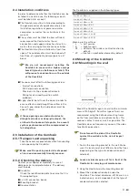
2.4 Installation  conditions

In order to determine whether the ComfoAir can be 
installed in a certain area, the following aspects 
must be taken into account:

  The ComfoAir must be installed according to 

the general and locally applicable safety and 
installation regulations of power and water 
companies, as well as the instructions in this 
manual.

  The system must be fitted to allow sufficient 

room around the ComfoAir for the air 
connections and supply and exhaust ducts as 
well as for carrying out maintenance activities.

  The ComfoAir must be installed in a frost-free 

space. The condensation must be drained off 
frost-free, at a gradient and incorporate a 'U' 
bend.


We do not recommend installing the 
ComfoAir in areas with a higher average 
humidity (such as bathroom or toilet). This 
will prevent condensation on the outside 
of the ComfoAir.

  The room must offer the following provisions:

  -   Air duct connections.
  -  230V electrical connection.
  -  Provisions for the condensation drain.
  -  Wiring for an wired 3-position switch 
   (optional).

  A gap should be left near the doors in order to 

ensure effective and draughtfree airflow in the 
house. A gap under the inside doors must be 
atleast 10mm. 

 If these openings are obstructed, due to 
draught excluders or deep-pile carpet, the 
airflow in the house will stagnate. As a result, 
system performance will be compromised or 
fail altogether.

2.5 Installation of the ComfoAir
2.5.1 Transport and unpacking

Take the necessary precautions when transporting 
and unpacking the ComfoAir.

 Make sure the packing material is disposed 
of in an environmentally friendly manner.

2.5.2  Checking the delivery

Contact your supplier immediately in case of 

damage or an incomplete delivery. The delivery 

must include:

   ComfoAir;

  Check the identification plate to ensure that it is 

the required type.

  4 x 45O connection bends;

  Mounting bracket;

 Documentation.

The ComfoAir is supplied in the following types:

Type

ComfoAir 350 Basic L

ComfoAir 350 Basic R

ComfoAir 350 Basic L RF

ComfoAir 350 Basic R RF

ComfoAir 350 Basic L VV

ComfoAir 350 Basic R VV

ComfoAir 350 Basic L VV RF

ComfoAir 350 Basic R VV RF

Meaning of the suffixes:

*   L  

=  Left version

*   R  

=  Right version

*   RF 

=  Contains the wireless control function by 


 default.

*   VV   = Contains a preheater element by default

2.6 Mounting of the ComfoAir
2.6.1 Mounting on the wall

Mount the ComfoAir against a wall with a minimum 
mass of 200 kg/m2. For other types of wall, we 
recommend using the Zehnder mounting frame 
on the floor (available as an optional extra). This 
reduces contact noise as much as possible. The 
ComfoAir does not require any space at the sides 
for effective operation.

 Do not mount the side of the ComfoAir 
against the wall due to the risk of impact 
sound.

1.  Fasten the mounting bracket to the wall. Make 

sure it is level and at least 878mm from the floor 
(depending on the type of condensation drain 
selected).

 Leave a minimum space of 1m in front of the 
ComfoAir for carrying out maintenance.

2.  Hang the ComfoAir on the mounting bracket.
3.  Mount the condensation drain under the 

ComfoAir. The stated dimension of 235 mm is an 
indication only, and is dependent on the type of 
condensation drain selected.

Содержание ComfoAir 350

Страница 1: ...ComfoAir 350 Installer manual Cooling Fresh Air Clean Air Heating...

Страница 2: ...has been compiled with the utmost care The publisher cannot be held liable for any damage caused as a result of missing or incorrect information in this manual In case of dis putes the Dutch version o...

Страница 3: ...ain 8 2 7 Commissioning the ComfoAir 9 2 7 1Display on the unit 9 2 7 2 P menus for the user 10 2 7 3 P menus for the installer 12 2 8 Programming air specifications 15 2 9 Maintenance by the installe...

Страница 4: ...EN 4...

Страница 5: ...warranty for a period of 24 months after fitting up to a maximum of 30 months after the date of manufacture Warranty claims may only be submitted for material faults and or construction faults arising...

Страница 6: ...e ComfoAir throughout its life Instructions with regard to cleaning or replacing the filters of the intake and exhaust valves must be carefully observed The specifications stated in this document may...

Страница 7: ...ent fan HE High efficient heat exchanger F Control circuit board H1 with connections for the fans the bypass the Preheater element temperature sensors T1 to T4 the 3 position switch with or without ma...

Страница 8: ...325 m3 h at 235 Pa 1 77 A Electricity Power supply 230 50 V Hz Cos phi 0 50 0 60 Connecting Power 1 59 kW Maximum Power Pre heater 1 35 kW Leakage current 1mA Supply fan noise level at 0 m Position Ve...

Страница 9: ...50 0 60 Connecting Power 1 59 kW Maximum Power Pre heater 1 35 kW Leakage current 1mA Supply fan noise level at 0 m Position Ventilation capacity Sound power Low Setting 125 m3 h at 25 Pa 54 dB A Med...

Страница 10: ...10 2 3 Dimension sketch 801 35 214 761 180 851 845 702 160 151 354 348 264 161 572 625 269 172 172 CONDENSATION DRAIN LEFT HAND VERSION CONDENSATION DRAIN RIGHT HAND VERSION CONDENSATION DRAIN 32 OUTS...

Страница 11: ...g and unpacking the ComfoAir Make sure the packing material is disposed of in an environmentally friendly manner 2 5 2 Checking the delivery Contact your supplier immediately in case of damage or an i...

Страница 12: ...balanced ventilation system We recommend that the ventilation system is fitted with intake and exhaust valves made by Zehnder Outside air Exhaust air Supply air Return air ComfoAir 350 LEFT Return ai...

Страница 13: ...o P8 are intended solely for the installer The ComfoAir s bypass valve will not work for the first 4 minutes after a power cut unless the programme mode is activated 2 7 1 Display on the unit The Comf...

Страница 14: ...or x minutes and then automatically returns to the normal setting If any 3 position switch is operated during this lagging time the ComfoAir will instantly revert to the ventilation position as set at...

Страница 15: ...P35 Setting the capacity in of the supply fan in low position 16 98 nL HL 35 40 P36 Setting the capacity in of the supply fan in medium position 17 99 nL HL 50 70 P37 Setting the capacity in of the su...

Страница 16: ...ypass 0 No 1 Yes 1 The standard ComfoAir configuration includes a bypass Therefore leave the value at 1 P56 Setting the required air volume in the house nL normal air volume HL high air volume nL HL H...

Страница 17: ...P57 settings Following a general reset all settings and programmes need to be checked and set to the right value P76 Self testing the ComfoAir 0 1 activate 0 The LED s on the display will start blinki...

Страница 18: ...e house If no data are known Install the valves and open them as far as possible Measure the air volumes starting with the intake air and then the exhaust air If the measured air volumes deviate from...

Страница 19: ...2 Remove the handles B from the ComfoAir 3 Remove the filters from the ComfoAir 4 Release the front panel by unscrewing the screws C 5 Slide the front panel upwards and remove the front panel from th...

Страница 20: ...trol circuit board panel and fully remove the cables including the two grommets K 4 Remove the entire scroll casing by pressing the click fasteners L 5 Remove the inflow nozzle by pressing the click f...

Страница 21: ...ve supply air temperature A3 NTC sensor T3 is defective return air temperature A4 NTC sensor T4 is defective exhaust air temperature A5 Malfunction in the bypass motor A6 Malfunction in the Preheater...

Страница 22: ...screws Remove the cover panel Reconnect the NTC sensor Reconnect the power to the ComfoAir Yes No Yes No Is the resistance of the NTC sensor correct Replace the NTC sensor Replace the control circuit...

Страница 23: ...c panel in front of the control circuit board by unscrewing the two screws Activate the self test P76 on 1 Remove the cover panel Did the bypass motor preheater element motor run Yes Disconnect the po...

Страница 24: ...ol circuit board Replace the NTC sensor Yes No Is the resistance of the preheater element cable infinite Replace preheater element cable Yes No Are the connections at the preheater element correct Rep...

Страница 25: ...c panel in front of the control circuit board by unscrewing the two screws Remove the cover panel Activate the self test P76 on 1 Check the following Fan settings to low Supply valve s to far closed S...

Страница 26: ...e unit P74 on 1 Fil tEr Internal Filter is dirt y Press OK on the display for at least 4 seconds until the filter warning disappears Disconnect the power from the ComfoAir Remove the handles from the...

Страница 27: ...all plastic panel in front of the control circuit board by unscrewing the two screws Is there 230 VAC power present on the fan Yes No Disconnect the power from the ComfoAir Replace the control circuit...

Страница 28: ...frost protection operation Wait until the weather warms up Too noisy Fan bearings defective Replace the fan bearings Fan settings to high Change the fan settings Slurping noise Siphon is empty Siphon...

Страница 29: ...10 2 ComfoAir PCB 400300010 3 Temperature sensor T2 T4 in scroll casing of both fans 400300040 4 Temperature sensor T1 T3 in top of unit near the electronic carriage 400100030 5 Servo motor cable for...

Страница 30: ...n Black Grey Preheater Supply Exhaust White Yellow Blue Brown White Brown White Red Black Blue Yellow White Brown White Brown White Black Red Bypass valve Preheater valve Green Yellow Green Yellow Gre...

Страница 31: ...volt free contact T1 T4 T3 T2 Bypass valve Green Yellow Brown Blue Blue Brown Red Black White Brown White Brown White Yellow 0 10V Blue L1 Grey L2 Black L3 Brown N Blue CASING EXHAUST SUPPLY RJ45 VEN...

Страница 32: ...4 Company register Zwolle 05022293 EEC declaration of conformity Machine description Heat recovery units ComfoAir 350 series Complies with the following directives Machinery Directive 2006 42 EEC Low...

Страница 33: ...33 EN...

Страница 34: ...EN 34...

Страница 35: ...35 EN...

Страница 36: ...Zehnder Group Nederland B V Lingenstraat 2 8028 PM Postbus 621 8000 AP Zwolle T 31 38 429 69 11 F 31 38 422 56 94 ventilatie zehnder nl www zehnder nl ZGNL Manual_40010995 V0117 EN Subject to change...

Отзывы: