Page 5
2 GENERAL CHARACTERISTIC
2.1 TECHNICAL SPECIFICATION
Chopper for Separately Excited DC motors ................................................... 2.5 ÷ 5.5kW
Regenerative Braking.
Voltage Range ...................................................................................... 24 to 48 Volts DC
Maximum Field Current (all the versions ............................................................. 50 Amps
Armature Switching Frequency ............................................................................... 16kHz
Field Switching Frequency ........................................................................................ 1kHz
Maximum Ambient temperature ............................................................................. + 40°C
Minimum Ambient temperature ................................................................................ -30°C
Maximum temperature of Chopper ........................................................................ + 85°C
Resistance of field Winding ............................................................................. 0.3 to 0.6
W
VERSION
MAXIMUM CURRENT
BOOSTER CURRENT
VOLTAGE DROP AT
TOTAL CONDUCTION
24V / 500A
500A
580A
0.25V at 200A, 25°C
36V / 500A
500A
580A
0.25V at 200A, 25°C
48V / 350A
350A
400A
0.25V at 100A, 25°C
2.2 CONTROL UNITS
2.2.a Microswitches
- Microswitches should have a contact resistance lower than 0.1
W
, and a leakage
current lower than 100 µA.
- When full load current is being drawn, the voltage drop across the Key Switch con
tacts must be lower than 0.1V.
- If an Electromagnetic Brake is used, the Handle Microswitch must operate the Brake
Coil.
- The Microswitches send a voltage signal to the microprocessor when an operating
request (running) is made.
Содержание SEM2
Страница 15: ...Page 15 3 6 MECHANICAL DRAWING DIMENSIONS...
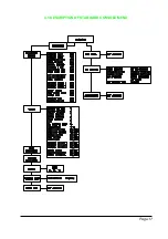
Страница 17: ...Page 17 4 3 DESCRIPTION OF STANDARD CONSOLE MENU...
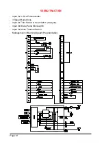
Страница 24: ...Page 24 5 4 SEM 2 TRACTION STANDARD WIRING DIAGRAMS...
Страница 38: ...INSTALLATION AND USER MANUAL CHOPPER SEM2...


