Page 28
9
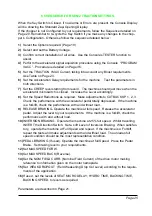
VFIELD NOT OK
This test is made at standby with the Main Contactor open. In this condition the
voltage on both the connections of field must be to around 1/ 2 VBatt. This alarm is
generated if the field voltage is different from this value. Possible causes:
a) Frame fault on the motor to chassis.
b) Incorrect connection of the field winding to the chopper.
c) Failure of the chopper in the section relative to the field.
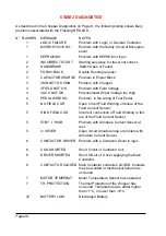
10 VACC NOT OK
This Alarm is generated if the accelerator output voltage differs more than 2V from
the acquired minimum during the PROGRAM VACC. Possible causes:
a) The track of the potentiometer has become open.
b) The potentiometer is not wired correctly.
c) The potentiometer itself is defective.
d) The values set in PROGRAM VACC routine have not remained or made cor-
rectly.
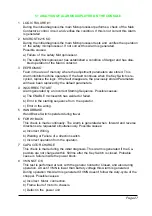
11 PEDAL WIRE KO
This Alarm is generated if potentiometer or wiring fault is detected. (NPOT or
PPOT are open circuit).
12 STBY I HIGH
This test is made during the initial diagnosis and at standby. The test verifies that
the current is zero. This Alarm disables the machine. Possible causes:
a) Defective current sensor.
b) Logic failure. First replace the logic. If fault remains replace the power unit.
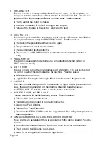
13 I = 0 EVER
This check is made during travel. If the current is not higher than a preset minimum
value, this Alarm is generated and the machine disabled. Possible causes:
see STBY I HIGH. Check the motor armature (brush connections).
14 HIGH FIELD CURR, NO FIELD CUR
Problem detected with the field winding current. Possible causes:
a) Tailure of the field current sensor.
b) Field cables not connected or incorrectly connected.
c) Open circuit Field Winding.
d) Failure of the Field Power Unit.
e) The Alarm No FIELD CURR could also be generated if the safety microprocessor
detects a problem.
15 CONTACTOR DRIVER, COIL SHORTED, DRIVER SHORTED
These Alarms are generated if there is a problem with the Main Contactor. Possible
causes:
a) the coil of the contactor is either short-circuit, open circuit, or not connected
b) The Contactor Coil Driver is short-circuit.
c) defect in the wiring to the contactor, or logic failure.
Содержание SEM2
Страница 15: ...Page 15 3 6 MECHANICAL DRAWING DIMENSIONS...
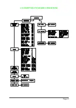
Страница 17: ...Page 17 4 3 DESCRIPTION OF STANDARD CONSOLE MENU...
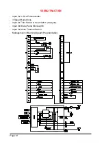
Страница 24: ...Page 24 5 4 SEM 2 TRACTION STANDARD WIRING DIAGRAMS...
Страница 38: ...INSTALLATION AND USER MANUAL CHOPPER SEM2...


