Page 12
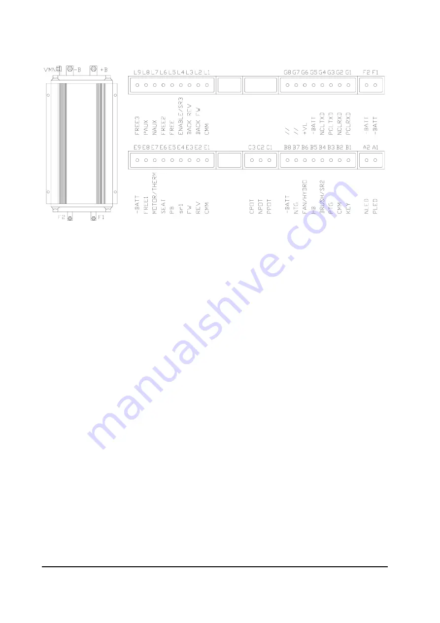
3.4 DESCRIPTION OF SEM 2 CONNECTORS.
PIN REFERENCE
DESCRIPTION
A1
PLED
Positive of Diagnostic Red Led.
A2
NLED
Negative of Diagnostic Red Led.
Output Current is 12mA, for this standard type Led.
B1
KEY
B+ Supply into logic Downstream of 10A Fuse & Key Switch.
B2
CMM
Positive Supply to Hand Brake and Brush / SR2 Microswitches.
B3
PTG
Positive Supply to Main Contactor.
B4
BRUSH / SR2 Input from motor brush switch (normally open), or Input from
second speed reduction switch (normally closed).
B5
HB
Input from Hand Brake Switch (normally closed).
B6
FAN / HYDRO Negative Output to Fan or Power Steer Contactor Coil.
B7
NTG
Negative Supply to Main Contactor.
B8
- BATT
Battery Negative.
C1
PPOT
Positive Output to Potentiometer (I max = 25mA).
C2
NPOT
Negative Output to Potentiometer.
C3
CPOT
Input from Potentiometer Wiper, or output of inductive device.
Содержание SEM2
Страница 15: ...Page 15 3 6 MECHANICAL DRAWING DIMENSIONS...
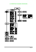
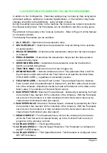
Страница 17: ...Page 17 4 3 DESCRIPTION OF STANDARD CONSOLE MENU...
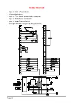
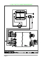
Страница 24: ...Page 24 5 4 SEM 2 TRACTION STANDARD WIRING DIAGRAMS...
Страница 38: ...INSTALLATION AND USER MANUAL CHOPPER SEM2...


