Page 21
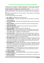
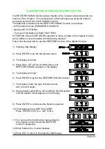
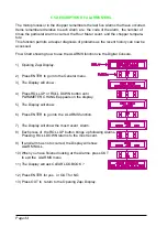
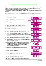
5.2 DESCRIPTION OF PARAMETERS THAT MAY BE PROGRAMMED
In addition to the Configuration, Parameter settings may be made by Zapi using stand-
ard default settings, settings to Customer Specifications, or the customer may make
changes according to the application, using a Digital Console.
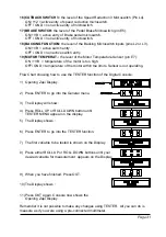
During the setting up procedure on the machine, the Console can remain connected to
the chopper during travel. The Parameters can be modified in real time, during opera-
tion.
Pay attention to the polarity of the Console Connector. Refer to Page 16 of this Manual
for connection details.
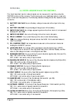
The following Parameters can be modified :
1
ACC. DELAY = Determines the acceleration ramp.
2
DECELER DELAY = Determines the deceleration ramp according to the accelera-
tor pedal position.
3
RELEASE BRAKING = Determines the deceleration ramp when the travel request
is released.
4
PEDAL BRAKING = Determines the deceleration ramp when the brake pedal is
operated during travel.
5
INVERSION BRAKING = Determines the deceleration ramp the the Direction
Switch is inverted during travel.
6
TRACTION IMAX = Maximum Current of the Chopper (A).
7
ARMA NOM.CURR. = Nominal Armature Current. This parameter fixes a limit for
the armature current above which the Field Current is at least the Nominal Value
(FIELD NOM.CURR.), regardless of accelerator position.
8
FIELD NOM. CURR. = Nominal Field Current. This parameter fixes the minimum
Field Current when the potentiometer is between 0% and 60% without total conduc-
tion of the Armature. Adjustment should be made with reference to the Data on the
Motor Label. (The indication of Nominal Field Current).
9
MAX SPEED FORW = Maximum Forward Speed, obtained by weakening the Field
Current after it has reached 100% conduction of the Armature. With the Parameter
set at level 0, the armature is in total conduction but the field current does not de-
crease below the Nominal value (low speed).
10 MAX SPEED BACK = Maximum Reverse Speed, obtained by weakening the Field
Current after it has reached 100% conduction of the Armature. With the Parameter
set at level 0, the armature is in total conduction but the field current does not de-
crease below the Nominal value (low speed).
11 WEAK DROPOUT = This Parameter fixes a limit on the Armature Current above
which the Field Current is increased linearly up to the Nominal Field Current (in
proportion to the armature current).
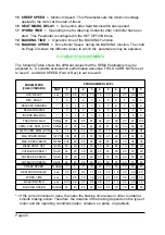
12 CUTBACK SPEED 1 = First Speed Reduction.
13 CUTBACK SPEED 2 = Second Speed Reduction. This Parameter is configured in
the SET OPTION Menu.
14 CUTBACK SPEED 3 = Third Speed Reduction. This Parameter is configured in the
SET OPTION Menu.
Содержание SEM2
Страница 15: ...Page 15 3 6 MECHANICAL DRAWING DIMENSIONS...
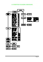
Страница 17: ...Page 17 4 3 DESCRIPTION OF STANDARD CONSOLE MENU...
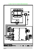
Страница 24: ...Page 24 5 4 SEM 2 TRACTION STANDARD WIRING DIAGRAMS...
Страница 38: ...INSTALLATION AND USER MANUAL CHOPPER SEM2...


