b.5 Installing the combustion air inlet pipe
For any described solution, two alternatives are possible:
•
Draw the air directly from the outside through a piping (internal Ø 50mm; max length 1,5m), connected to the air inlet
pipe on the back of the stove.
•
Draw the air directly from the installation room, given that in the proximity of the stove an air inlet pipe (minimum area
100 cm²) is installed on the sidewall, so that it communicates with the outside.
In both cases, periodically verify that nothing has obstructed the passage of the air.
IMPORTANT: This device cannot be used on a shared flue.
b.6 Connecting to the power supply
Verify if the electrical system and the mains outlets present the capacity to support the maximum absorption of the stove, which
is reported on the plate.
Make sure the system is provided with a norm-compliant earthing and differential switch.
The stove must be connected to a norm-compliant, 230v – 50Hz mains outlet. Avoid using adapters, multiple sockets or
extensions.
Make sure the cable connecting to the system is not touching any hot surface of the stove; also make sure the stove is not
treading on the cable.
The engine of the stove is protected by a fuse, which is inserted in the general switch on the back of the stove.
Remember always to unplug the stove from the power supply before performing any maintenance and/or control intervention.
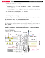
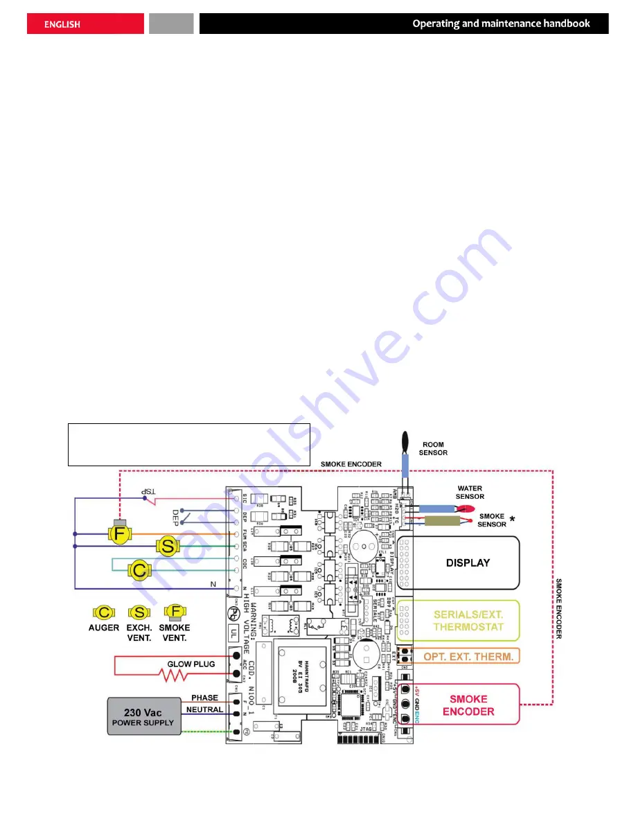
ELECTRICAL DIAGRAM
DEP=NEGATIVE PRESSURE SWITCH
TSP=PELLET COMPARTMENT SAFETY THERMOSTAT
* OBSERVE THE POLES OF THE THERMOCOUPLE TO ENSURE
CORRECT OPERATION
12
Содержание HEBE
Страница 1: ...PELLET STOVE HEBE OPERATING AND MAINTENANCE HANDBOOK...
Страница 2: ......
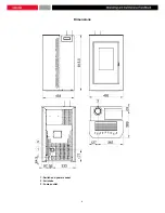
Страница 8: ...Dimensions 1 Switch and power socket 2 Air intake 3 Fumes outlet 8...
Страница 22: ...Fig 13f Fig 13 22...
Страница 34: ...34...
Страница 35: ...35...

