


184
YORK INTERNATIONAL
FORM 201.18-NM9 (602)
System Switches OFF:
This message indicates that the system switch on the
Microprocessor Board for the respective system is in
the OFF position. A system can only run if the system
switch is in the ON position. The switch for System 1
and System 2 should normally be in the ON position
for all models. Switches for System 3 and 4 should only
be in the ON position for three and four compressor
chillers respectively. See Section 1.11, Figure 79, page
179 for the location of the system switches.
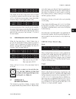
Anti-Recycle Timers:
The anti-recycle timer message shows the amount of
time remaining before a compressor can be called to
restart. These 300 - 600 sec. timers begin timing when
a compressor starts, although a minimum of two min-
utes must always elapse after a compressor shuts down,
before it may again restart. If a power failure occurs,
the anti-recycle timers will reset to 120 seconds after
power is restored. The purpose of the timer is to allow
for motor cooling to dissipate the heat generated by in-
rush current at start-up.
Anti-Coincidence Timers:
The anti-coincident timer guards against two or more
compressors starting simultaneously. This avoids ex-
cessive instantaneous starting currents. A minimum of
60 seconds between compressor starts is maintained
even if demand is present and the anti-recycle timers
are timed out. The display shows the time before the
respective compressor can start. This display will only
appear after the anti-recycle timers have timed out.
Run Permissive Contacts OPEN:
This display indicates that an external cycling contact
and/or the flow switch connected to terminals 13 & 14
in the Logic Section(s) of the control panel(s) is/are
open. Whenever the contact(s) is /are open, the No Run
Permissive message will be displayed and the indicated
system will not run.
System Loading Requirement:
This message indicates that chilled liquid temperature is
below the point where the microprocessor will bring the
lead system on and/or that the loading sequence has not
loaded the chiller far enough to bring the lag system on.
The lag system will display this message until the load-
ing sequence is ready for the lag system to start.
2.3
UNIT WARNINGS
Unit Warnings are often caused by conditions which
require operator intervention to start the unit or extreme
operating conditions. All setpoints and programmable
values should be checked, if a chiller shutdown oc-
curred, before restarting the chiller. Unit Warnings are
not logged into the HISTORY BUFFER.
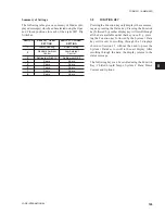
Low Battery Warning
On power-up the microprocessor will check the RTC
(Real Time Clock) memory back-up battery to make
sure it is still operational. Provided the battery checks
out, operation will continue normally. If a check is made
and the battery has failed, the microprocessor will not
allow the chiller to run and the above Status message
will appear.
If a low battery condition exists, the
micro will restore programmed cutouts,
setpoints, and schedules to their default
values.
Once a low battery condition is detected, the only way
to run the chiller is to use the Manual Override key -
see Section 7.4, page 210. This allows reprogramming
of setpoints, cutouts, and schedule.
The U13 RTC chip should be replaced as soon as pos-
sible with Part # 031-00955-000. Otherwise, the chiller
will shutdown and lose all programmed points, and re-
quire a MANUAL OVERRIDE restart, if a power fail-
ure occurs.
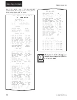
Pump Down:
S Y S
#
D S C H
L I M I T I N G
S Y S
#
D S C H
L I M I T I N G
S Y S
#
A R
T I M E R
0
S
S Y S
#
A R
T I M E R
1 2 0
S
S Y S
#
C O M P
R U N N I N G
S Y S
#
A C
T I M E R
2 2
S
! !
L O W
B A T T E R Y
! !
C H E C K
P R O G / S E T P / T I M E
S Y S
#
N O
R U N
P E R M
S Y S
#
N O
R U N
P E R M
S Y S
#
N O
C O O L
L O A D
S Y S
#
N O
C O O L
L O A D
S Y S
1
P U M P I N G
D O W N
S Y S
2
P U M P I N G
D O W N
Micro Panel Contents
Содержание eco YCAS Series
Страница 65: ...65 YORK INTERNATIONAL FORM 201 18 NM9 602 This page intentionally left blank 7...
Страница 77: ...77 YORK INTERNATIONAL FORM 201 18 NM9 602 This page intentionally left blank 7...
Страница 81: ...81 YORK INTERNATIONAL FORM 201 18 NM9 602 LD04179 7...
Страница 83: ...83 YORK INTERNATIONAL FORM 201 18 NM9 602 7 LD04181 Box Information continued from page 82...
Страница 97: ...97 YORK INTERNATIONAL FORM 201 18 NM9 602 This page intentionally left blank 7...
Страница 103: ...FORM 201 18 NM9 602 YORK INTERNATIONAL YORK INTERNATIONAL 103 103A LD04267 FORM 201 18 NM9 602...
Страница 163: ...163 YORK INTERNATIONAL FORM 201 18 NM9 602 COMPRESSOR COMPONENTS CONT D FIG 69 COMPRESSOR COMPONENTS CONT D LD03670 7...


