YOKOGAWA ZR202S Скачать руководство пользователя страница 90


<8. Detailed Data Setting>

8-9

IM 11M13A01-04E

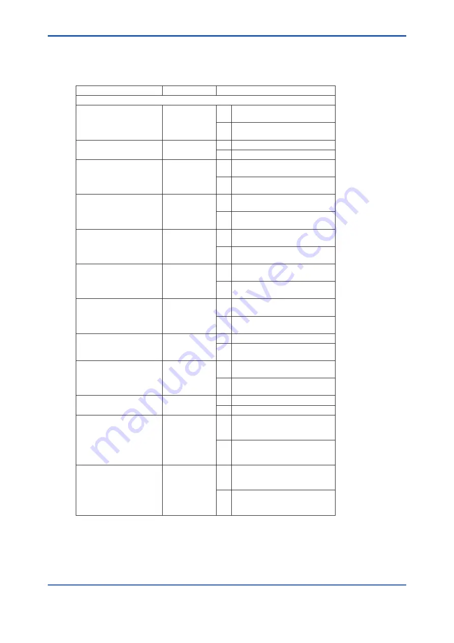
8.5.2  Setting Contact Output

Set the contact outputs following Table 8.10.

Table 8.10 

Parameter Codes for Contact Output Setting

Set item 

Parameter code 

Set value

Contact output 1

Operation 

E10 

0 Operated in closed status. 

(Normally de-energized)

1 Operated when open. (Normally 

energized) 

(Note 1)

Error 

E20 

0 Not operated if an error occurs.
1 Operated if an error occurs.

High-high alarm 

E21 

0 Not operated if a high-high alarm 

occurs.

1 Operated if a high-high alarm 

occurs. 

(Note 2)

High alarm 

E22 

0 Not operated if a high alarm 

occurs.

1 Operated if a high alarm occurs. 

(Note 2)

Low alarm 

E23 

0 Not operated if a low alarm 

occurs.

1 Operated if a low alarm occurs. 

(Note 2)

Low-low alarm 

E24 

0 Not operated if a low-low alarm 

occurs.

1 Operated if a low-low alarm 

occurs. 

(Note 2)

During maintenance 

E25 

0 Not operated during 

maintenance.

1 Operated during maintenance 

(see Subsection 8.3.1).

During calibration 

E26 

0 Not operated during calibration.
1 Operated during calibration (see 

Subsection 8.3.1).

Output range change 

E27 

0 Not operated when changing 

ranges.

1 Operated when changing 

ranges. 

(Note 3)

During warm-up 

E28 

0 Not operated during warming up.
1 Operated during warming up.

Calibration gas 

pressure decrease 

E29 

0 Not operated while a calibration 

gas pressure decrease, contact 

is being closed.

1 Operated while a calibration gas 

pressure decrease, contact is 

being closed. 

(Note 4)

Unburnt gas 

detection

E32 

0 Not operated while an unburnt 

gas detection, contact is being 

closed.

1 Operated while an unburnt 

gas detection, contact is being 

closed. 

(Note 5)

Note 1:  Contact output 2 remains closed. 

Note 2:  The oxygen concentration alarm must be preset (see Section 8.4).

Note 3:  Range change answer-back signal. For this action, the range change must be preset during the setting of contact inputs  

(see Section 8.5). 

Note 4:  Calibration gas pressure decrease answer-back signal. Calibration gas pressure decrease must be selected beforehand 

during the setting of contact inputs.

Note 5:  Non-combusted gas detection answer-back signals. “Non-combusted gas” detection must be selected during the setting of 

contact inputs.  

Содержание ZR202S

Страница 1: ...User s Manual Model ZR202S Integrated type Explosion proof Zirconia Oxygen Analyzer IM 11M13A01 04E IM 11M13A01 04E 6th Edition ...

Страница 2: ...rs specifications Please read it along with this manual The EXAxt ZR Integrated type Explosion proof Zirconia Oxygen Analyzer has been developed for combustion control in various industrial processes There are several version of this analyzer so you can select one that matches your application Optional accessories are also available to improve measurement accuracy and automate calibration An optim...

Страница 3: ...sion drawing for each equipment 3 Installation Installation method for each equipment 4 Piping Examples of piping in two standard system configurations 5 Wiring Wiring procedures such as Power supply wiring Output signal wiring or others 6 Components Major parts and functions are described 7 Startup Basic procedure to start operation of EXAxt ZR Chapter 7 enables you to operate the equipment immed...

Страница 4: ...iii IM 11M13A01 04E Introduction ATEX Documentation This is only applicable to the countries in the European Union GB DK I E NL SF P F D S LT LV PL EST SLO H BG RO M CZ SK GR ...

Страница 5: ...ision 1 Groups B C and D Class II III Division 1 Groups E F and G T2 ZR202S D IECEx Ex db IIB H2T2 Gb Ex tb IIIC T300 C Db For the safe use of this equipment WARNING EXAxt ZR is very heavy Be sure not to accidentally drop it Handle safely to avoid injury Connect the power supply cord only after confirming that the supply voltage matches the rating of this equipment In addition confirm that the pow...

Страница 6: ...tained in this product but does not warrant that those will suit the particular purpose of the user Every effort has been made to ensure accuracy in the preparation of this manual However should any errors or omissions come to the attention of the user please contact the nearest Yokogawa Electric representative or sales office This manual does not cover the special specifications This manual may n...

Страница 7: ...ibes what special care the operator must exercise to avoid such risks CAUTION This symbol indicates that the operator must refer to the instructions in this manual in order to prevent the instrument hardware or software from being damaged or a system failure from occurring NOTE This symbol draws attention to information essential for understanding the operation and functions Protective Ground Term...

Страница 8: ...ation keys displays on the panel Enclosed in Ex MODE key Ex message display BASE Ex data display 102 lit 102 flashing Drawing for flashing Indicated by gray characters Flashing lit Displays on the LCD display panel 9 8 7 6 5 4 3 2 1 0 W V U T S R Q P O N M L K J I H G F E D C B A Alphanumerics Alphanumerics Alphanumerics LED Display LED Display LED Display Z Y ...

Страница 9: ... on the operation parameters initial data set before shipping from the factory Ensure that the initial data is suitable for the operation conditions before conducting analysis Where necessary set the instrument parameters for appropriate operation For details of setting data refer to chapters 7 to 10 When user changes the operation parameter it is recommended to note down the changed setting data ...

Страница 10: ... person with specialized knowledge l How to dispose the batteries This is an explanation about the new EU Battery Directive DIRECTIVE 2006 66 EC This directive is only valid in the EU Batteries are included in this product Batteries incorporated into this product cannot be removed by yourself Dispose them together with this product When you dispose this product in the EU contact your local Yokogaw...

Страница 11: ...anty stated in instruction manual Failure caused by usage of software hardware or auxiliary equipment which Yokogawa did not supply Failure due to improper or insufficient maintenance by user Failure due to modification misuse or outside of specifications operation which Yokogawa does not authorize Failure due to power supply voltage frequency being outside specifications or abnormal Failure cause...

Страница 12: ...xi IM 11M13A01 04E Introduction ...

Страница 13: ...oof Zirconia Oxygen Analyzer 2 4 2 1 3 ZO21R Probe Protector 2 11 2 2 ZA8F Flow Setting Unit 2 12 2 3 ZO21S Standard Gas Unit 2 14 2 4 Other Equipment 2 15 2 4 1 Stop Valve L9852CB G7016XH 2 15 2 4 2 Check Valve K9292DN K9292DS 2 15 2 4 3 Air Set 2 16 2 4 4 Pressure Reducing Valve for Gas Cylinder G7013XF G7014XF 2 17 2 4 5 ZR202A Heater Assembly 2 17 3 Installation 3 1 3 1 Installation of ZR202S ...

Страница 14: ... Cable Specifications 5 4 5 2 2 Wiring Procedure 5 4 5 3 Wiring Power and Ground Terminals 5 5 5 3 1 Wiring for Power Line 5 5 5 3 2 Wiring for Ground Terminals 5 5 5 4 Wiring for Contact Output 5 6 5 4 1 Cable Specifications 5 6 5 4 2 Wiring Procedure 5 6 5 5 Wiring for Contact Input 5 6 5 5 1 Cable Specifications 5 6 5 5 2 Wiring Procedure 5 7 6 Components 6 1 6 1 ZR202S Zirconia Oxygen Analyzer...

Страница 15: ... 3 Selection of Output Mode 8 2 8 2 4 Default Values 8 2 8 3 Output Hold Setting 8 3 8 3 1 Definition of Equipment Status 8 3 8 3 2 Preference Order of Output Hold Value 8 5 8 3 3 Output Hold Setting 8 5 8 3 4 Default Values 8 5 8 4 Oxygen Concentration Alarms Setting 8 6 8 4 1 Setting the Alarm Values 8 6 8 4 2 Alarm Output Actions 8 6 8 4 3 Alarm Setting 8 7 8 4 4 Default Values 8 8 8 5 Contact ...

Страница 16: ...5 10 1 11 Robustness of a Cell 10 5 10 1 12 Heater On Time Ratio 10 6 10 1 13 Oxygen Concentration with time constant 10 6 10 1 14 Maximum Oxygen Concentration 10 6 10 1 15 Minimum Oxygen Concentration 10 6 10 1 16 Average Oxygen Concentration 10 6 10 1 17 Span and Zero Correction Ratios 10 6 10 1 18 History of Calibration Time 10 7 10 1 19 Time 10 7 10 1 20 Software Revision 10 7 10 2 Operational...

Страница 17: ...r 11 9 11 3 Replacement of Flowmeter for Automatic Calibration Unit 11 11 12 Troubleshooting 12 1 12 1 Displays and Remedies When Errors Occur 12 1 12 1 1 Error Types 12 1 12 1 2 Remedies When an Error Occurs 12 2 12 2 Displays and Remedies When Alarms are Generated 12 4 12 2 1 Alarm types 12 4 12 2 2 Remedies When Alarms are Generated 12 5 12 3 Measures When Measured Value Shows an Error 12 9 12 ...

Страница 18: ...Blank Page ...

Страница 19: ...s so that an optimal combustion control system can be obtained Some examples of typical system configuration are illustrated below 1 1 EXAxt ZR System Configuration The system configuration should be determined by the conditions e g whether the calibration is to be automated and whether flammable gas is present and requires safety precautions The system configuration can be classified into two bas...

Страница 20: ...Explosion proof Zirconia Oxygen Analyzer F1 2E ai Span gas 2 Non hazardous Area Hazardous Area 1 Figure 1 2 Example of System 2 1 2 EXAxt ZR System Components 1 2 1 System Components System Components ZR202S Integrated type Zirconia Oxygen Analyzers ZO21R Probe Protector for Zirconia Oxygen Analyzers ZO21S Standard Gas Unit Automatic Calibration Unit for integrated type Analyzer L9852CB G7016XH St...

Страница 21: ... 1 General Specifications 2 1 1 Standard Specifications Measured Object Oxygen concentration in combustion exhaust gas and mixed gas excluding inflammable gases May not be applicable corrosive gas such as ammonia and chlorine is present Contact with YOKOGAWA and its agency Measurement System Zirconia system Measurement Range 0 01 to 100 vol O2 Output Signal 4 to 20 mA DC maximum load resistance 55...

Страница 22: ...oof ZR202S B Applicable Standard FM3600 1998 FM3615 1989 FM3810 2005 ANSI NEMA 250 1991 Type of protection Explosion proof for Class I Division 1 Groups B C and D Dust ignitionproof for Class II III Division 1 Groups E F and G Enclosure Rating NEMA 4X Temperature Class T2 CSA Explosion proof ZR202S C Applicable Standard C22 2 No 0 M1991 C22 2 No 0 4 04 C22 2 No 0 5 1982 C22 2 No 25 1966 C22 2 No 3...

Страница 23: ...led over voltage category specifies impulse withstand voltage Category II is for electrical equipment Pollution degree indicates the degree of existence of solid liquid gas or other inclusions which may reduce dielectric strength Degree 2 is the normal indoor environment Safety Conforms to EN 61010 1 EN 61010 2 030 CAN CSA C22 2 No 61010 1 certified UL Std No 61010 1 certified EMC Conforms to EN 6...

Страница 24: ...50 Ω depending on quantity of field devices connected to the loop multi drop mode Note HART is a registered trademark of the HART Communication Foundation Contact Output Signal Two points one is fail safe normally open Contact Input Signal Two points Sample Gas Temperature 0 to 700 C It is necessary to mount the cell using Inconel cell bolts when the temperature measures more than 600 C High tempe...

Страница 25: ...robe Mounting Angle Horizontal to vertically downward Case Aluminum alloy Finish Polyurethane corrosion resistance coating Weight Insertion length of 0 4m approx 15 kg ANSI 150 4 Insertion length of 1 0m approx 17 kg ANSI 150 4 Insertion length of 1 5m approx 19 kg ANSI 150 4 Insertion length of 2 0m approx 21 kg ANSI 150 4 Functions Display Function Displays values of the measured oxygen concentr...

Страница 26: ...ease flameout gas detection answer back of contact input Converter Output One mA analog output 4 to 20 mA DC maximum load resistance of 550 Ω with mA digital output HART minimum load resistance of 250 Ω Range Any setting between 0 to 5 through 0 to 100 vol O2 in 1 vol O2 or partial range is available Maximum range value minimum range value 1 3 or more For the log output the minimum range value is ...

Страница 27: ...an be skipped Zero calibration gas concentration setting range 0 3 to 100 vol O2 in 0 01 vol O2 Span calibration gas concentration setting range 4 5 to 100 vol O2 in 0 01 vol O2 Use nitrogen balanced mixed gas containing 0 to 10 vol O2 scale of oxygen for standard zero gas and 80 to 100 vol O2 scale of oxygen for standard span gas Calibration period Date time setting maximum 255 days 23 hours ...

Страница 28: ...12 Failure alarm up scale Output status at CPU failure and hardware error is 21 0 mA or more 12 1 The thickness of the flange depends on its dimensions 2 Inconel probe bolts and U shape pipe are used Use this option for high temperature use ranging from 600 to700 C 3 Specify either CV or SV option code 4 Specify either SCT or PT option code 5 No need to specify the option codes CV and SV since the...

Страница 29: ...150 2 RF 304 SS JIS ANSI Class 150 3 RF304 SS JIS ANSI Class 150 4 RF 304 SS JIS DIN PN10 DN50 304 SS JIS DIN PN10 DN80 304 SS JIS DIN PN10 DN100 304 SS JIS JIS 5K 65 FF 304 SS JIS JIS 10K 65 FF 304 SS JIS JIS 10K 80 FF 304 SS JIS JIS 10K 100 FF 304 SS JIS JPI Class 150 4 RF 304 SS JIS JPI Class 150 3 RF 304 SS JIS Westinghouse 152 4 190 5 228 6 165 200 220 155 175 185 210 229 190 155 120 6 152 4 ...

Страница 30: ...4 or 1 4NPT Female Zero gas inlet VERTICAL INSTALL Span gas inlet Unit mm 348 3 MAX 44 214 40 244 66 5 40 Rc1 4 or 1 4NPT Female Rc1 4 or 1 4NPT Female Reference gas inlet Rc1 4 or 1 4NPT Female Zero gas inlet AUTOMATIC CALIBRATION UNIT HORIZONTAL INSTALL Display Terminal box 258 166 5 156 3 F2 3E ai Standard Accessories Item Parts No Q ty Description Fuse A1113EF 1 3 15 A Allen wrench L9827AB 1 F...

Страница 31: ... m Approx 12 16 kg JIS ANSI Installation Bolts nuts and washers are provided for detector probe protector and process side flange Model and Codes Model Suffix code Option code Description ZO21R L Probe Protector 0 to 700 C Insertion length 100 150 200 1 05 m 3 5 ft 1 55 m 5 1 ft 2 05 m 6 8 ft Flange 1 J A JIS 5K 65 FF SUS304 ANSI Class 150 4 FF SUS304 Style code B Style B 1 Thickness of flange dep...

Страница 32: ...e gas 0 1 to 1 0 L min Painting Baked epoxy resin Dark green Munsell 2 0 GY 3 1 0 5 or equivalent Tube Connections Rc1 4 or 1 4FNPT Reference Gas Pressure Clean air supply of sample gas pressure plus approx 50 kPaG or sample gas pressure plus approx 150 kPaG when a check valve is used Pressure at inlet of the Flow Setting Unit Maximum 300 kPaG Reference Gas Consumption Approx 1 5 L min Calibration...

Страница 33: ...ent air Approx 1 5 L min Air Set REF OUT SPAN GAS IN 20 20 35 35 35 35 35 70 32 8 222 8 235 8 140 180 7 Reference gas outlet Calibration gas outlet ø6 Hole Span gas inlet Zero gas inlet JIS 50A 60 5mm mounting pipe Instrument air inlet F2 5E ai Air pressure without check valve sample gas pressure approx 50 kPaG with check valve sample gas pressure approx 150 kPaG Piping connection port A ZA8F J C ...

Страница 34: ...illed pressure Approx 686 kPaG at 35 C Composition 0 95 to 1 0 vol O2 N2 balance Power Supply 100 110 115 200 220 240 V AC 10 50 60 Hz Power Consumption Max 5 VA Case material SPCC cold rolled steel sheet Paint Color Mainframe Munsell 2 0 GY3 1 0 5 equivalent Cover Munsell 2 8 GY6 4 0 9 equivalent Piping Ø6 х Ø4 mm flexible tube connection Weight Approx 3 kg Model and Codes Model Suffix code Optio...

Страница 35: ...ck Valve K9292DN K9292DS This valve is mounted on the calibration gas line directly connected to the detector This valve prevents the sample gas from entering the calibration gas line Although it functions as a stop valve operation is easier than a stop valve as it does not require opening closing at each calibration Screw a check valve instead of a stop valve into the calibration gas inlet of the...

Страница 36: ...er 316 SS JIS G7004XF K9473XG Primary Pressure Max 1 MPaG Secondary Pressure 0 02 to 0 5 MPaG Connection Rc1 4 or 1 4 FNPT with joint adapter Weight Approx 1 kg Part No Description G7004XF Joint Rc 1 4 Material Zinc alloy K9473XG Joint 1 4 FNPT with joint adapter Material Zinc alloy Adapter 316 SS JIS External Dimensions Ø74 Primary Secondary 88 Max 210 max 55 Approx 122 Secondary pressure gauge P...

Страница 37: ...valve Approx 112 Inlet F2 10E ai Outlet Part No G7013XF G7014XF Outlet Rc1 4 1 4 NPT female with adapter Secondary pressure gauge Primary pressure gauge Secondary safety valve Primary safety valve Approx 82 Approx 59 Approx 163 Approx 174 Unit mm 2 4 5 ZR202A Heater Assembly Model and Codes Model Suffix code Option code Description ZR202A Heater Assembly for ZR202S Length 1 040 070 100 150 200 0 4...

Страница 38: ...ternal Dimensions K9470BX L Weight kg ZR202A 040 ZR202A 070 ZR202A 100 ZR202A 150 ZR202A 200 Approx 0 8 Approx 1 2 Approx 1 6 Approx 2 2 Approx 2 8 Jig for change K9470BX Ø21 7 30 Unit mm Model Codes F2 11E ai 552 852 1152 1652 2152 L 12 Ø 45 ...

Страница 39: ...e following should be taken into consideration when installing the analyzer 1 Easy and safe access to the analyzer for checking and maintenance work 2 Ambient temperature of not more than 55 C and the terminal box should not be affected by radiant heat 3 A clean environment without any corrosive gases 4 No vibration 5 The sample gas satisfies the specifications described in Chapter 2 6 No sample g...

Страница 40: ... GLANDS Take care not to generate mechanical sparking when accessing to the analyzer and peripheral devices in hazardous area Note 4 Maintenance and Repair The analyzer modification or parts replacement by other than authorized representative of Yokogawa Electric Corporation is prohibited and will void the certification Note 5 Cable Entry The threaded type of cable entry is marked beside the cable...

Страница 41: ...005 ANSI NEMA 250 1991 Type of protection Explosion proof for Class I Division 1 Groups B C and D Dust ignitionproof for Class II III Division 1 Groups E F and G Enclosure Rating NEMA 4X Temperature Class T2 Note 2 Wiring All wiring shall comply with National Electrical Code ANSI NEPA 70 and Local Electrical Code In hazardous area wiring shall be in conduits as shown in the figure WARNING SEALALL ...

Страница 42: ... C Analyzer for use in hazardous area Note 1 Applicable Standard C22 2 No 0 M1991 C22 2 No 0 4 04 C22 2 No 0 5 1982 C22 2 No 25 1966 C22 2 No 30 M1986 C22 2 No 94 M91 C22 2 No 61010 1 04 Certificate Number 1649642 Type of protection Explosion proof for Class I Division 1 Groups B C and D Dust ignitionproof for Class II III Division 1 Groups E F and G Enclosure Type 4X Temperature Class T2 Note 2 W...

Страница 43: ...0079 31 2013 Certificate Number IECEx KEM 06 0006X The symbol X placed after certificate number indicates that the equipment is subjected to special conditions for safe use Refer to Note 6 Type of protection Ex db IIB H2 Gb Ex tb IIIC T300ºC Db Temperature class for Ex db T2 The maximum surface temperature for Ex tb T300ºC Degree of protection of enclosure IP66 Note 2 Wiring All wiring shall compl...

Страница 44: ...ss protection of at least IP66 Note 6 Special conditions for safe use Electrostatic charge may cause an explosion hazard Avoid any actions that cause the generation of electrostatic charge such as rubbing with a dry cloth If it is mounted in the area where the use of Ex tb apparatus is required it shall be installed in such a way that the risk from electrostatic discharges and propagating brush di...

Страница 45: ...E ai vertical Bounds of the probe insertion hole area Flange matches the detector size horizontal Type Outside diameter of probe Standard 52 mm in diameter With probe protector 60 5 mm in diameter Four hole flange Eight hole flange 1 1 Figure 3 5 Example of forming probe insertion hole 3 1 7 Installation of the Probe Detector CAUTION The cell sensor at the tip of the probe is made of ceramic zirco...

Страница 46: ...the sensor assembly mounting screws four bolts at the probe tip are not loose 3 When the probe is mounted horizontally the calibration gas and reference gas inlet should face downward Direction of the sample gas flow Mount the protector so that the notch is on the downstream side of gas flow Unit mm F3 4E ai 1050 1550 2050 Gasket t1 5 Calibration gas inlet Reference gas inlet Probe top Figure 3 6 ...

Страница 47: ...t The unit weighs approximately 2 to 3 5 kg 2 Mount the flow setting unit on the pipe by tightening the nuts with the U bolt so that the metal fitting is firmly attached to the pipe F3 5E ai Figure 3 7 Pipe Mounting Wall Mounting 1 Make a hole in the wall as illustrated in Figure 3 8 223 140 F3 6E ai 4 Ø6 hole or M5 screw Unit mm Figure 3 8 Mounting holes 2 Mount the flow setting unit Remove the p...

Страница 48: ...ground 4 Turn the insulation resistance tester ON and measure the insulation resistance 5 After testing remove the tester and connect a 100 kΩ resistance between the crossover wiring and ground to discharge 6 Testing between the heater terminal and ground contact output terminal and ground analog output input terminal and the ground can be conducted in the same manner 7 Although contact input term...

Страница 49: ...ause clogging of the piping or incorrect calibration Be sure to conduct leakage test after setting the piping Basically apply instrument air dehumidified by cooling to the dew point 20 C or lower and removing any dust oil mist and the like for the reference gas CAUTION Do not loosen or remove any Flame Arrestor of gas inlet outlet during piping The detector modification or parts replacement by oth...

Страница 50: ...ration gas inlet of the equipment 4 1 1 Piping Parts for System 1 Referring to Table 4 1 check that the parts required for your system are ready Table 4 1 Piping Parts Equipment Piping location Parts Name Description Integrated type Explosion proof Zirconia Oxygen Analyzer Calibration gas inlet Stop valve or check valve Stop valve L9852CB or G7016XH recommended by YOKOGAWA Check valve K9292DN or K...

Страница 51: ...low setting unit and the ZR202S analyzer to a 6 mm O D x 4 mm I D or nominal size 1 4 inches or larger stainless steel pipe F4 2E ai Stop valve or check valve Piping for the reference gas inlet 6mm O D by 4mm I D Stainless steel pipe Piping for the calibration gas inlet 6mm O D by 4mm I D Stainless steel pipe Piping for the reference gas outlet 6mm O D by 4mm I D Stainless steel pipe Figure 4 2 Pi...

Страница 52: ...tact output see Sec 7 9 2 and adjust zero gas pressure reducing valve and calibration gas needle valve so that zero gas flow is within the permitted range Next check span gas calibration contact output and adjust air set so that span gas flow is within the permitted range 100 to 240 V AC Automatic Calibration Unit Reference gas Calibration gas Zero Contact input Analog output contact output Digita...

Страница 53: ...ATIC CALIBRATION UNIT HORIZONTAL INSTALL Terminal box 258 166 5 Display 180 MAX 44 40 60 66 5 40 166 5 45 160 AUTOMATIC CALIBRATION UNIT Rc1 4 or 1 4NPT Female Span gas inlet Rc1 4 or 1 4NPT Female Reference gas inlet Rc1 4 or 1 4NPT Female Zero gas inlet Piping Diagram SPAN IN REF IN ZERO IN F4 5E ai Calibration gas Reference gas ZR202S body Span gas solenoid valve Span gas flowmeter Reference ga...

Страница 54: ...f the operator and marked as the power supply switch of this equipment Wiring procedure Wiring should be made according to the following procedure 1 Be sure to connect the shield of the shielded line to FG terminal of the analyzer 2 The most outer sheath of the signal line and the power cable should be stripped off to the minimum necessary length 3 Signal will be affected by noise emission when th...

Страница 55: ...able O D for the cable gland size Protective grounding should have the grounding resistance of 100 Ω or less 5 1 1 Terminals for the External Wiring Remove the terminal cover on the opposite side of the display to gain access to the external wiring terminals DI L N FG AO F FG F5 1E ai 2 C DO 2 DO 1 1 Figure 5 1 Terminals for External Wiring ...

Страница 56: ... Hz Digital output Contact input 2 The protective grounding for the analyzer shall be connected either the protective ground terminal in the equipment or the ground terminal on the case Standard regarding grounding Ground to earth ground resistance 100 Ω or less Figure 5 2 Wiring Connection 5 1 3 Mounting of Cable Gland For each wiring inlet connection of the equipment mount the conduit appropriat...

Страница 57: ...1 M4 screws are used for the terminals Use crimp on terminals appropriate for M4 terminal screws for cable connections Ensure that the cable shield is connected to the FG terminal of the equipment 2 Be sure to connect and polarities correctly CAUTION Before opening the cover loosen the lock screw If the screw is not loosened first the cover will be improperly engaged to the body and the terminal b...

Страница 58: ...ither the ground terminal of the equipment case M5 or the terminal inside of the equipment M4 Proceed as follows 1 Keep the ground resistance of 100 Ω or less JIS D style Class 3 grounding 2 When connecting the ground wiring to the ground terminal of the equipment case be sure that the lock washer is in contact with the case surface see Figure 5 5 3 Ensure that the jumper plate is connected betwee...

Страница 59: ... contacts used 5 4 2 Wiring Procedure 1 M4 screws are used for the terminals Use crimp on terminals appropriate for M4 terminal screws for cable connections 2 The contact output relays are rated 30 V DC 3A 250 V AC 3A Connect a load e g pilot lamp and annunciator within these limits 5 5 Wiring for Contact Input The analyzer can execute specified function when receiving contact signals To use these...

Страница 60: ...Each cable should be equipped with the corresponding crimp contact 2 The ON OFF level of this contact input is identified by the resistance Connect a contact input that satisfies the descriptions in Table 5 2 Table 5 2 Identification of Contact Input ON OFF Closed Open Resistance 200 Ω or less 100 kΩ or more ...

Страница 61: ...Blank Page ...

Страница 62: ...alyzer Terminal box Explosion proof Probe This part is inserted in the furnace Selectable of length from 0 4 0 7 1 0 1 5 2 0 m Flange used to mount the detector Selectable from JIS ANSI or DIN standard models F6 1E ai Bolt Washer Pipe support U shaped pipe Metal O ring Flame arrestor assembly mounting screw Sensor cell Contact Screw Probe Calibration gas pipe opening Filter Flame arrestor assembly...

Страница 63: ...etting Unit ZERO IN REF IN SPAN IN ZERO IN REF IN SPAN IN F6 3E ai Flowmeter for Span gas Flowmeter for Span gas Flowmeter for Reference gas Flowmeter for Reference gas Flowmeter for Zero gas Flowmeter for Zero gas Horizontal mounting Vertical mounting Span gas flow setting valve Span gas flow setting valve Reference gas flow setting valve Reference gas flow setting valve Zero gas flow setting val...

Страница 64: ...bration F7 1E ai Place in normal operation Check piping and wiring connections Set up valves Supply power Confirm equipment type setting Select gas to be measured Set output ranges Check current loop Check contact action Calibrate analyzer Set detailed data Figure 7 1 Startup Procedure For system tuning by HART communication refer to the IM 11M12A01 51E HART Communication Protocol ...

Страница 65: ...nut NOTE The calibration gas flow setting will be described later Fully close the needle valve in the flow setting unit 7 3 Supplying Power to Analyzer CAUTION To avoid temperature changes around the sensor it is recommended that the power be continuously supplied to the Oxygen Analyzer if it is used in an application where its operations and suspensions are periodically repeated It is also recomm...

Страница 66: ...on after reaching the rightmost position of the digit 2 Selects Yes or No 3 When you touch this key together with the ENT key the previous display then appears or the operation will be cancelled Used to change values If you continuously touch this key the value of the digit will increase continuously e g from 1 to 2 to 3 for numeric data or from A to B to C for alphabetic characters and finally re...

Страница 67: ... Display Configuration The parameter codes provided for the equipment are used to control the equipment display panels see below By selecting appropriate parameter codes you can conduct calibration and set operation parameters Figure 7 5 shows the configuration of display items The parameter codes are listed in groups of seven which are briefly described in Table 7 2 To enter parameters you first ...

Страница 68: ...fferent password Table7 3 Parameter Code Selection Switch operation Display Description ENT 21 0 Warm up is complete and the basic panel is now displayed ENT PASSno Continuously touch the ENT key for at least three seconds to display PASSno ENT 0000 Touch the ENT key again This allows you to change the leftmost digit that is flashing ENT 1000 Set the password 1102 If you touch the key the digit th...

Страница 69: ... the right one more digit This enables you to change numeric value to 1 ENT A01 Touch the key again to return the position of the digit that is flashing to A Continuously touch the key and the position of the digit that is flashing will move continuously to the right ENT b01 If you touch the key once character A will change to b ENT C01 Touch the key once to change to C ENT d01 Continuously touch ...

Страница 70: ...rrently set value is 0 0 ENT 00 0 Touch the key to move the position of the digit that is flashing to the digit to be changed Continuously touch the key and the position of the digit that is flashing will move continuously to the right ENT 09 0 Touch the key to set the numeric value to 9 Continuously touch the key and the numeric value will change in sequence from 0 to 1 to 2 to 3 to 8 to 9 and ba...

Страница 71: ...word has been entered ENT F01 Touch the key to switch to Group F If an unwanted alphabetic character after F has been entered continuously touch the key to return to the original ENT 0 Touch the ENT key for confirmation If 0 zero is entered the oxygen analyzer is already set If 1 one is entered the humidity analyzer has been set Change the setting following the steps below ENT 0 Continuously touch...

Страница 72: ... is entered the oxygen concentration in a wet gas is already set If the oxygen concentration in a dry gas is to be entered follow the steps below to set 1 one ENT 1 Continuously touch the key and the position of the digit will change from 1 to 0 to 1 to 0 Release the ENT key when 1 one is displayed ENT 1 Touch the ENT key The numeric value will flash ENT 1 Touch the ENT key again to stop the value...

Страница 73: ...itch to the parameter code selection display ENT C11 Set the oxygen concentration at 20 mA Touch the key to move the position of the digit that is flashing to the right ENT C12 Touch the key to enter the numeric value to 2 ENT 025 Touch the ENT key to display the current set value ENT 025 Touch the key to move the position of the digit that is flashing to the right ENT 020 Touch the key to change ...

Страница 74: ...output is then issued ENT G01 Touch the ENT key once again to switch to the parameter code selection display At that point the current output returns to the normal value ENT Basic panel display Touch the key together with the ENT key to return to the basic panel display The symbol indicates that the key is being touched Light characters indicates that the digits are flashing 7 9 Checking Contact I...

Страница 75: ...G11 Touch the ENT key once again to switch to the parameter code selection display The contact output then returns to the original state ENT Basic panel display Touch the key together with the ENT key to return to the basic panel display This is not required if you proceed to make another setting The displayed numeric values indicate the measurement gas concentration The symbol indicates that the ...

Страница 76: ... to enter 1 ENT G11 Touch the key to move the position of the digit that is flashing to the right one digit ENT G15 Touch the key to enter 5 ENT 0 Touch the ENT key to have 0 flash The solenoid valve remains closed ENT 1 Touch the key to enter 1 ENT 1 Touch the ENT key The flashing continues ENT 1 Touch the ENT key again to stop the flashing and the solenoid valve will be open to let the calibrati...

Страница 77: ...t is flashing to the right one digit ENT G21 Touch the key to enter 2 ENT 0 Touch the ENT key 0 is displayed with the contact input open If the contact input is closed the display will be 1 one This enables you to check whether or not the wiring connections have been properly made or not ENT G21 Touch the ENT key once again to switch the parameter code selection display ENT Basic panel display Tou...

Страница 78: ...ibration Setup Set the following three items before carrying out a calibration Parameter codes for these set items are listed in Table 7 13 1 Mode setting There are three calibration modes manual semi automatic and automatic Select the desired mode This section uses manual mode for calibration 2 Oxygen concentration in zero gas Enter the zero gas oxygen concentration for calibration 3 Oxygen conce...

Страница 79: ...ave all the digits flash ENT 000 98 Touch the ENT key again to stop the flashing ENT b01 Touch the ENT key once again to switch to the parameter code selection display Set the span gas concentration by above procedure set 21 ENT b03 Next set the calibration mode Switch the parameter code to B03 ENT 0 Touch the ENT key to display the currently set value If it is 0 manual calibration you can leave i...

Страница 80: ... the B10 display ENT CAL If you touch the ENT key again CAL then flashes To cancel the above touch the key and ENT key together the display will return to the B10 display ENT SPAn Y If you touch the ENT key again SPAn Y appears Y is flashing If you omit the span calibration touch the key and change Y to N If you touch the ENT key the display then jumps to ZEro Y ENT 21 00 Touch the ENT key to disp...

Страница 81: ...nges to the zero gas value When the display becomes stable proceed to the next step To cancel the above touch the key and ENT key together then the display returns to ZEro Y ENT 0 89 If you touch the ENT key all the digits flash At that point no calibration is conducted yet ENT CALEnd Touch the ENT key again to get the measured value to agree with the zero gas concentration Close the zero gas flow...

Страница 82: ...he output damping has been set for the current output values involving the output damping are displayed CAUTION If you set 3 in the parameter code A00 or F08 be sure to select Oxygen Concentration in the following mA output setting see Section 8 2 Current Output Setting 8 2 Current Output Setting This section describes setting of the analog output range Table 8 2 shows parameter codes for the set ...

Страница 83: ...ed up CAUTION When you select logarithmic mode the minimum output remains constant at 0 1 O2 and the parameter C11 display remains unchanged 8 2 2 Entering Output Damping Constants If a measured value adversely affected by a rapid change in the sample gas oxygen concentration is used for the control means frequent on off actions of the output will result To avoid this the analyzer allows the setti...

Страница 84: ...on of Equipment Status 1 During warm up During warm up is the time required after applying power until the sensor temperature stabilizes at 750 C and the equipment is in the measurement mode This status is that the sensor temperature is displayed on the basic panel 2 During maintenance During maintenance is the time from when a valid password is entered in the basic panel display to enable the par...

Страница 85: ...libration In a semi automatic calibration during calibration is the time starting when a calibration instruction is executed with an infrared switch or a contact input to make a series of calibrations until the preset output stabilization time elapses In an automatic calibration during calibration is the time starting when automatic calibration is carried out at the calibration start time until th...

Страница 86: ... 5 Parameter Codes for Output Holding Set items Parameter code Set value During warm up C04 0 4 mA 1 20 mA 2 Holds Set value During maintenance C05 0 Without hold feature 1 Last measured value 2 Holds set values During calibration C06 0 Without hold feature 1 Last measured value 2 Holds set values During error occurrence C07 0 Without hold feature 1 Last measured value 2 Holds set values Note C07 ...

Страница 87: ...s set the delay time and allow for hysteresis for alarm canceling under the alarm output conditions as Figure 8 2 shows When the delay time is set an alarm will not be issued so quickly even if the measured value differs from the steady state and enters the alarm setpoint range If the measured value remains within the alarm setpoint range for a certain period of time for the preset delay time an a...

Страница 88: ...steresis set value and the preset delay time elapses so the alarm is canceled 8 4 3 Alarm Setting Set the alarm setpoints following Table 8 7 listing parameter codes Table 8 7 Parameter Codes for Oxygen Concentration Alarms Set item Parameter code Set value Oxygen concentration high high alarm setpoint D01 0 100 O2 Oxygen concentration high alarm setpoint D02 0 100 O2 Oxygen concentration low alar...

Страница 89: ... contact outputs Be sure to observe relay contact ratings For details see Section 2 1 General Specifications The following sets forth the operation mode of each contact output Contact output 1 you can select open or closed contact when the contact is operated For contact output 2 contact is closed The relay for contact output 1 is energized when its contacts are closed and vice versa Accordingly w...

Страница 90: ... calibration 1 Operated during calibration see Subsection 8 3 1 Output range change E27 0 Not operated when changing ranges 1 Operated when changing ranges Note 3 During warm up E28 0 Not operated during warming up 1 Operated during warming up Calibration gas pressure decrease E29 0 Not operated while a calibration gas pressure decrease contact is being closed 1 Operated while a calibration gas pr...

Страница 91: ... analyzer is delivered or if data are initialized contact outputs are by default as shown in Table 8 11 Table 8 11 Contact Output Default Settings Item Contact output 1 Contact output 2 High high alarm High alarm Low alarm Low low alarm Error O During warm up O Output range change During calibration During maintenance O Calibration gas pressure decrease Unburnt gas detection Operating contact stat...

Страница 92: ...e heater power will be switched off An one to 11 second time interval single output signal is available as a contact signal If this operation starts the sensor temperature decreases and an error occurs To restore it to normal turn the power off and then back on or reset the analyzer CAUTION To conduct a semi automatic calibration be sure to set the Calibration setup mode to Semi automatic or Autom...

Страница 93: ...ey to move the position of the digit that is flashing to the right one digit ENT 00 06 21 Touch the key to change to 2 ENT 00 06 21 Touch the key to move the position of the digit that is flashing to the right one digit ENT 07 18 Let the rightmost character flash and touch the key to display the time Continuously touch the key then the date and time are alternately displayed Displayed on the left ...

Страница 94: ...he average maximum and minimum oxygen concentration values Periods over which average is calculated and periods over which maximum and minimum values are monitored can be set ranging from 1 to 255 hours If the set ranges are beyond the limits specified an Err will be displayed Table 8 15 Parameter Codes for Average Maximum and Minimum Values Set item Parameter code Set range Units Periods over whi...

Страница 95: ...per unit quantity of fuel m3 kg or m3 m3 m Air ratio X Fuel coefficient determined depending on low calorific power of fuel m3 kg or m3 m3 3 in Table 8 8 Z Absolute humidity of the atmosphere kg kg Figure 8 17 water vapor caused by combustion and water vapor contained in the exhaust gas 8 7 3E siki actual exhaust gas including water vapor per fuel water vapor contained in air for combustion x 100 ...

Страница 96: ...Hydrogen in fuel weight w Moisture content in fuel weight Hx Same as numeric value of H1 For solid fuel Amount of water vapor in exhaust gas Gw 1 100 1 24 9h w m kg Theoretical amount of air 1 01 x H1 1000 0 56 m kg Low calorific power H1 Hh 25 9h w kJ kg X value 1 11 0 106 1000 x Hx m m where w Total moisture content in use weight h Hydrogen content weight The average hydrogen content of coal min...

Страница 97: ... 022 0 020 0 018 0 016 0 014 0 012 0 010 0 008 0 006 0 004 0 002 0 000 0 2 4 6 8 10 12 14 16 18 20 22 24 26 28 30 32 34 36 38 40 2 0 2 4 6 8 10 12 14 16 18 20 22 24 26 28 30 32 34 36 38 35 37 39 33 31 29 27 25 Wet bulb temperature C Absolute humidity kg kg Dry bulb temperature C F8 4E ai Figure 8 4 Absolute Humidity of Air ...

Страница 98: ... 1 6 4 2 25 0 2 0 20 0 53 0 50 5 25 9 2 6 3 9 0 1 8 0 20428 18209 3391 3349 37883 34074 102055 93976 125496 115868 12767 12642 39750 69638 62991 99070 128452 10758 12642 35820 63744 59060 91255 118623 4 455 0 603 9 015 24 63 30 37 2 390 2 390 9 570 16 74 14 35 23 91 31 09 0 45 0 45 0 98 3 10 3 90 1 0 2 0 2 0 1 0 3 0 4 0 1 10 0 02 1 88 4 10 4 90 1 0 2 0 3 0 2 0 4 0 5 0 3 60 1 01 7 17 19 5 24 0 1 89...

Страница 99: ...4 Setting Purging Purging is to remove condensed water in the calibration gas pipe by supplying a span calibration gas for a given length of time before warm up of the detector This prevents cell breakage during calibration due to condensed water in the pipe Open the solenoid valve for the automatic calibration span gas during purging and after the purge time has elapsed close the valve to start w...

Страница 100: ...ve electrode on the opposite side There the electrons are released and the ions return to the oxygen molecules This reaction is indicated as follows Negative electrode O2 4e 2 O 2 Positive electrode 2 O 2 O2 4 e The electromotive force E mV between the two electrodes generated by the reaction is governed by Nernst s equation as follows E RT nF ln Px Pa Equation 1 where R Gas constant T Absolute te...

Страница 101: ...is necessary To meet this requirement an analyzer calibration is conducted so that a calibration curve is obtained which corrects the deviation from the theoretical cell electromotive force 9 1 2 Calibration Gas A gas with a known oxygen concentration is used for calibration Normal calibration is performed using two different gases a zero gas of low oxygen concentration and a span gas of high oxyg...

Страница 102: ...n correction ratio C A x 100 Correctable range 0 18 Cell electromotive force mV Calibration curve before correction Corrected calibration curve theoretical calibration curve Zero origin Span gas concentration Zero gas concentration Span origin Oxygen concentration vol O2 F9 2E ai Figure 9 2 Calculation of a Two point Calibration Curve and Correction Ratios using Zero and Span Gases Figure 9 3 show...

Страница 103: ...f zero correction ratio Recorded the past ten zero correction ratios 3 Response time You can monitor the response time provided that a two point calibration has been done in semi automatic or automatic calibration 4 Cell s internal resistance The cell s internal resistance gradually increases as the cell sensor deteriorates You can monitor the values measured during the latest calibration However ...

Страница 104: ... When Manual calibration is selected Manual calibration only can be conducted This mode does not allow semi automatic calibration with a contact input nor automatic calibration even when its start up time has reached When Semi automatic calibration is selected This mode enables manual and semi automatic calibrations to be conducted The mode however does not allow automatic calibration even when it...

Страница 105: ...time The calibration time is the time required from starting the flow of the calibration gas to reading out the measured value The set calibration time is effective in conducting both zero and span calibrations The calibration time set ranges from 00 minutes 00 seconds to 60 minutes 59 seconds Figure 9 4 shows the relationship between the calibration time and hold output stabilization time Analog ...

Страница 106: ...the calibration start day no calibration will be conducted Table 9 1 Parameter Codes for Calibration Setting Set Item Parameter code Set value Engineering unit Zero gas concentration B01 Set Zero gas concentration O2 Span gas concentration B02 Set Span gas concentration O2 Calibration mode B03 0 Manual calibration 1 Semi automatic and manual 2 Automatic semi automatic and manual Hold Output stabil...

Страница 107: ...lashes until the set output stabilization time elapses ENT Basic panel display If the output stabilization time elapses the basic panel display then appears Output holding will be released The symbol indicates that the corresponding keys are being touched and the light characters indicate flashing indicates that both are displayed alternately 2 To start calibration using an contact input follow th...

Страница 108: ...10 Other Functions 10 1 Detailed Display Select the desired parameter code to display the detailed operation data see Table 10 1 Parameter Codes for Detailed Operation Data NOTE Refer to Section 8 1 Setting Display Item for parameter code A00 ...

Страница 109: ...Zero correction ratio 5 A15 Cold junction voltage mV A66 Zero correction ratio 6 A16 Current output mA A67 Zero correction ratio 7 A20 Cell response time Seconds A68 Zero correction ratio 8 A21 Cell internal resistance Ω A69 Zero correction ratio 9 A22 Cell robustness A70 Calibration history 0 YY MM DD HH MM A23 Heater on time ratio A71 Calibration history 1 YY MM DD HH MM A24 Oxygen concentration...

Страница 110: ...nternal where the electronics is installed temperature of equipment which compensates for the cold junction temperature for a thermocouple measuring the cell temperature If this temperature exceeds 85 C the electronics may fail When the ZR202 Analyzer is used the maximum C J temperature will be 150 C If the internal temperature exceeds this take measures to reduce the temperature such as by not ex...

Страница 111: ...s cell voltage Table 10 2 Oxygen Concentration Vs Cell Voltage cell temperature 750 C O2 0 1 0 2 0 3 0 4 0 5 0 6 0 7 0 8 0 9 mv 117 83 102 56 93 62 87 28 82 36 78 35 74 95 72 01 69 41 O2 1 2 3 4 5 6 7 8 9 mv 67 09 51 82 42 88 36 54 31 62 27 61 24 21 21 27 18 67 O2 10 21 0 30 40 50 60 70 80 90 mv 16 35 0 7 86 14 2 19 2 23 1 26 5 29 5 32 1 O2 100 mv 34 4 T10 2E ai 10 1 6 Thermocouple Voltage The cel...

Страница 112: ...on of the cell cannot be found only by changes in cell s internal resistance however Those changes in the cell s internal resistance will be a hint to knowing the sensor is degrading The updated values obtained during the calibration are displayed 10 1 11 Robustness of a Cell The robustness of a cell is an index for predicting the remaining life of a sensor and is expressed as one of four time per...

Страница 113: ...specified in the Averaging display are displayed If the setup period elapses the minimum oxygen concentration that has been displayed so far will be cleared and a new minimum oxygen concentration will be displayed If the setup period of time is changed the current minimum oxygen concentration will be displayed for more details see Subsection 8 7 2 earlier in this manual 10 1 16 Average Oxygen Conc...

Страница 114: ...ntration vol O2 F10 2E ai Figure 10 2 Span gas and Zero gas Correction Ratios 10 1 18 History of Calibration Time The calibration conducted dates and times for the past ten calibrations are stored in memory 10 1 19 Time The current date and time are displayed These are backed up by built in batteries so no adjustment is required after the power is switched off The following shows an example of dis...

Страница 115: ... a parameter code based initialization Table 10 4 lists the initialization items by a parameter code and default values Table 10 4 Parameter Codes for Initialization Parameter code Data to be initialized F30 All data F31 Data in Group A F32 Data in Group B F33 Data in Group C F34 Data in Group D F35 Data in Group E F36 Data in Group F CAUTION When Data in Group F are initialized by the parameter c...

Страница 116: ...T 1000 Enter the password 1255 for initialization ENT 1000 ENT 1200 ENT 1200 ENT 1250 ENT 1250 ENT 1255 ENT 1255 After you enter the password and then touch the ENT key all the digits flash ENT USr Go Touch the ENT key again to display USr Go ENT USr Go Touch the ENT key once more All the digits then flash for two to three seconds and data initialization starts ENT F30 The initialization is comple...

Страница 117: ...f an EEPROM write error occurs For details on error occurrence consult Chapter 12 Troubleshooting later in this manual If any of the above problems occurs the equipment turns off the power to the detector heater To cancel the error reset the equipment following the steps below or turn the power off and then back on Note Make sure that before resetting or restarting the power that there is no probl...

Страница 118: ...econds ENT 0000 Touch the ENT key again to switch to the password entry display ENT 1000 Enter the password 1102 Intermediate switch operations omitted ENT 1102 ENT A01 ENT G01 Change the parameter code to G30 ENT G01 ENT G30 ENT All the digits light up Touch the ENT key to execute resetting The symbol indicates that the corresponding keys are being touched and the light characters indicate flashi...

Страница 119: ...rection ratio 5 A15 Cold junction voltage mV A66 Zero correction ratio 6 A16 Current output mA A67 Zero correction ratio 7 A20 Cell response time Seconds A68 Zero correction ratio 8 A21 Cell internal resistance Ω A69 Zero correction ratio 9 A22 Cell robustness A70 Calibration history 0 YY MM DD HH MM A23 Heater on time ratio A71 Calibration history 1 YY MM DD HH MM A24 Oxygen concentration with ti...

Страница 120: ...tput stabilization time 0 minutes 0 seconds to 60 minutes 59 seconds MM SS 10 minutes 0 seconds B05 Calibration time 0 minutes 0 seconds to 60 minutes 59 seconds MM SS 10 minutes 0 seconds B06 Calibration interval 0 days 0 hours to 255 days 23 hours DD HH 30 days 0 hours B07 Calibration start date and time YY MM DD HH MM 00 01 01 00 00 B08 Calibration procedure 0 Zero and span Zero and span 1 Span...

Страница 121: ...conds 0 second C31 Set value during warm up 2 4 to 21 6 mA 4 mA C32 Set value during maintenance 2 4 to 21 6 mA 4 mA C33 Set value during calibration 2 4 to 21 6 mA 4 mA C34 Set value in abnormal state 2 4 to 21 6 mA 3 4 mA Note C07 and C34 is not displayed when option code C2 or C3 NAMUR NE 43 compliant is specified Alarm related Items in Group D Code Item Tuning Engineering unit Default setting ...

Страница 122: ...ontact output 1 0 Action with closed contact normally de energized Action with closed contact 1 Action with open contact normally energized E20 Contact output 1 error 0 No action No action 1 Action E21 Contact output 1 high high alarm 0 No action No action 1 Action E22 Contact output 1 high alarm 0 No action No action 1 Action E23 Contact output 1 low alarm 0 No action No action 1 Action E24 Conta...

Страница 123: ... monitored 1 to 255 hours Hours 24 hours F20 Amount of water vapor in exhaust gas 0 to 5 m3 kg m3 1 0 m3 kg m3 F21 Theoretical amount of air 0 to 20 m3 kg m3 1 0 m3 kg m3 F22 X value 0 to 19 99 1 0 F23 Absolute humidity of the atmosphere 0 to 1 kg kg 0 1 kg kg F30 Initializing all data F31 Initializing data in group A F32 Initializing data in group B F33 Initializing data in group C F34 Initializi...

Страница 124: ...w 10 5 1 Standard Gas Unit Component Identification Applies the power to operate the pump to supply the span gas Carrying case Flow checker Span gas valve Checks the zero and span gas flow Controls the span gas air flow Zero gas valve regulator Tube connection Cover screws six pcs Pump Supplies span gas air Gas cylinder Contains the zero gas A gas of 7 Nl is charged to 700 kPa Clamp Clamps the gas...

Страница 125: ... the bottom of the cylinder with the clamp 5 Take note of the oxygen concentration of the sealed gas indicated on the gas cylinder and replace the carrying case Enter the oxygen concentration of the sealed gas using the parameter code B01 as a zero gas oxygen concentration Also check that no piping is disconnected Thus the work of installing a gas cylinder is completed However gases in the cylinde...

Страница 126: ...these steps 1 Use the needle of the zero gas valve CHECK GAS to puncture a hole in the gas cylinder installed as described in Subsection 10 5 2 Fully clockwise turn the valve regulator by hand 2 Next adjust the flow rate to 600 60 ml min the flow check ball stops floating on the green line when the valve is slowly opened Turn the regulator of the zero gas valve back slowly counterclockwise At that...

Страница 127: ... IM 11M13A01 04E WARNING Store the standard gas unit with the gas cylinder mounted where the ambient temperature does not exceed 40 C Otherwise the gas cylinder may explode Store the spare gas cylinders under the same condition ...

Страница 128: ...valve regulator slowly counterclockwise To check the flow rate use the calibration flowmeter 2 Adjust the flow rate After the measured oxygen concentration has stabilized touch the ENT key then all the digits will flash Touch the ENT key again to display ZEro Y 3 Close the span gas flow setting valve to stop the span gas air flow If the valve shaft has a lock nut be sure to tighten the lock nut to...

Страница 129: ...Blank Page ...

Страница 130: ...ouch the probe if it has been in operation immediately just before being checked The sensor at the tip of the probe heats up to 750 C during operation If you touch it you will get burned CAUTION Do not subject the probe to shock or cool it rapidly The sensor is made of ceramic zirconia If the detector is dropped or bumped into something the sensor may be damaged and no longer work Do not reuse a m...

Страница 131: ...libration gas inlet at about 600 ml min and insert the rod into the tube 3 mm inside diameter However be careful not to insert the rod deeper than 40 cm 4 Clean the U shaped pipe The pipe can be rinsed with water However it should be dried out thoroughly before reassembly 5 Restore all components you removed for cleaning Follow Subsection 11 1 2 to restore all components in their original position...

Страница 132: ...hen sand further with a higher grade of sandpaper No 1500 or so or use an appropriate metal brush to eliminate any sharp protrusions on the groove The contact s resistance should be minimized Use cell assemblies manufactured in or after Sept 2000 the serial number on the side of the cell assembly should be 0J000 or later for example 0K123 1AA01 etc F11 2E ai Flame arrestor assembly Bolts four Wash...

Страница 133: ...ct Being careful not to cause irregularities in the pitch of the coil spirals i e not to bend the coil out of shape place it in the ringed groove properly so that it forms a solid contact Groove in which the contact E7042BS is placed F11 3E ai Figure 11 3 Installing the Contact 2 Next make sure that the O ring groove on the flange surface of the sensor cell is clean Install the metal O ring in tha...

Страница 134: ... subject it to strong vibrations or shock Additionally the heater assembly reaches high temperatures and is subjected to high voltages So maintenance services should be performed after the power is off and the heater assembly temperature has returned to normal room temperature For details refer to IM11M12A01 21E Heater Assembly NOTE If the heater strut assembly cannot be removed because a screw ha...

Страница 135: ... 11 Inspection and Maintenance 11 6 IM 11M13A01 04E A A View A A 25 1 2 3 4 5 6 7 8 9 10 11 13 14 16 14 13 17 19 20 21 22 23 24 24 24 F11 4E ai 18 Figure 11 4 Exploded View of Detector ...

Страница 136: ...e Push the two caps 20 into the associated opening of the connector 13 Insert the plate 17 aligning it with the groove of the cap 20 and tighten it with the screw 25 If you attempt to insert the calibration gas and reference gas pipes into the connector 13 without disassembling the connector 13 the O ring may be damaged Tighten screw 19 to the plate 17 of heater strut assembly until connector 13 c...

Страница 137: ...or portion and dusts may stick to it If operation is restarted in this condition the sensor which is heated up to 750 C may become permanently contaminated Consequently the dusts can make the sensor performance very lower If a large amount of water is condensed the sensor can be broken and never be used To prevent the above nonconformity take the following action when stopping operation 1 If possi...

Страница 138: ...he grounded metal part to discharge any static electricity 1 Remove the display cover Figure 11 6 2 Remove the three screws that are located toward you among the four screws shown in Figure 11 7 Loosen the remaining one 3 Move the electronics up to remove it F11 6E ai Cover of Display F11 7E ai SCREW Figure 11 6 Cover of Display Figure 11 7 Location of Screw 4 Disconnect the three connectors from ...

Страница 139: ...he fuse is installed properly these are directly connected with connectors 9 Tighten the four screws in their positions 10 Replace and tighten the display cover properly If the cover is not tightened sufficiently the infrared switches will not operate correctly Fuse rating Check the rating of the fuse and that it satisfies the following Maximum rated voltage 250 V Maximum rated current 3 15 A Type...

Страница 140: ...sitions and tighten an extra 5 10 when reassembling After tightening do a liquid leakage test Vertical mounting Horizontal mounting C C B B C B A A A F11 10E ai Connect piping pairs A A B B C C D D Fixing screw pairs Flame Arrestor Flame Arrestor Fitting Flame Arrestor Fitting Fitting Figure 11 10 Fixing Flowmeter WARNING Do not loosen or remove any Flame Arrestor of gas inlet outlet during piping...

Страница 141: ...Blank Page ...

Страница 142: ...tput if the error Parameter code E20 is set up for Contact output setting for that contact refer to Section 8 5 Contact Output Setting 4 Changes the analog output status to the one set in Output hold setting refer to Section 8 3 Output Hold Setting The content of errors that are displayed include those shown in Table 12 1 Displayed alternately Err 01 F12 1E ai Figure 12 1 Table 12 1 Types of Error...

Страница 143: ...cess to the two connectors four connectors for the optional automatic calibration unit as indicated in Figure 12 2 Check these connectors are properly connected 6 If Err 01 still occurs the electronics may be defective Contact your local Yokogawa service or sales representative Err 02 Heater Temperature Failure This error occurs if the detector heater temperature does not rise during warm up or if...

Страница 144: ...fective Consult your local Yokogawa service or sales representative Err 03 A D Converter Failure Err 04 Writing to memory Failure A D Converter Failure It is suspected that a failure has occurred in the A D converter mounted in the electrical circuits inside the converter Writing to memory Failure It is suspected that a failure has occurred in an operation writing to the memory EEPROM mounted in t...

Страница 145: ...d semi automatic calibration refer to Subsection 9 1 3 Compensation AL 08 EMF stabilization time up alarm Generated when the cell sensor voltage is not stabilized even after the calibration time is up in automatic and semi automatic calibration AL 10 Cold junction temperature alarm Occurs when an equipment internal temperature exceeds 85 C AL 11 Thermocouple voltage alarm Generated when thermocoup...

Страница 146: ...t of carrying out re calibration deterioration of or damage to the cell sensor is suspected as the cause of the alarm Replacement of the cell sensor with a new one is necessary However before replacement carry out the following Check the cell voltages when passing the zero gas and span gas a Display the cell voltage with the parameter code A11 b Check whether or not the value of the displayed cell...

Страница 147: ...splay Span gas conc is selected in Calibration setup the set value should agree with the concentration of span gas actually used b The calibration gas tubing should be constructed so that the span gas does not leak 2 If no alarm is generated as a result of carrying out re calibration it is suspected that improper calibration conditions were the cause of the alarm in the preceding calibration In th...

Страница 148: ...d the limits take appropriate measures such as applying heat insulating material to the furnace walls and adding a sun shield to keep out direct sunlight If this alarm occurs even when the ambient temperature is under 55 C the electronics may be defective Contact your local Yokogawa service or sales representative AL 11 Thermocouple Voltage Alarm This alarm is generated when the e m f voltage of t...

Страница 149: ...arm occurs removing power from the instrument may cause the clock to stop but should not affect stored parameters The internal clock is used for calibration and purge scheduling if you use this then after a battery alarm occurs until the battery is replaced be sure to check correct the date and time every time you turn on the power Corrective action When the battery low alarm occurs remember that ...

Страница 150: ...reference gas changes increases greatly If air at the detector installation site is used for the reference gas large change of moisture in the air may cause an error in measured oxygen concentration value vol O2 When this error is not ignored use a gas in which moisture content is constant such as instrument air in almost dry condition as a reference gas In addition change of moisture content in e...

Страница 151: ...4 Combustible components exist in the sample gas If combustible components exist in the sample gas they burn in the sensor and thus oxygen concentration decreases Check that there are no combustible components 5 Temperature of the sensor cell reaches 750 C or more If the sensor temperature is 750 C or higher this may indicate that sample gas has leaks into the reference gas side corrosion Also che...

Страница 152: ...477EA G7109YC K9470BK E7042DW K9470ZF K9470ZG E7042BR K9470BM K9473AN ZR01A01 01 ZR01A01 02 ZR01A01 05 ZR01A01 10 E7042BS K9470BJ E7042AY K9470ZK K9470ZL 1 4 4 1 1 1 1 1 1 1 1 1 Flame Arrestor Bolt M5x12 SUS316 stainless steel M5x12 inconel for Option code C Washer SUS316 stainless steel Bolts and Washers G7109YC x 4 E7042DW x 4 K9470BK x 4 E7042DW x 4 for Option code C Plate Pipe Pipe for Option ...

Страница 153: ......

Страница 154: ...h Edition Feb 2016 YK Hood for ZR202S ZR202G_F ai 1 Item Part No Qty Description 1 K9472UF 1 Hood Automatic Calibration Unit SPAN IN REF IN ZERO IN 10PSI SS 2C2 10 NUPRO 1 Item Part No Qty Description 1 K9473XC 1 Flowmeter ...

Страница 155: ......

Страница 156: ...l ZO21S Zirconia Oxygen Analyzer High Temperature Humidity Analyzer Standard Gas Unit CMPL 11M3D1 01E 1st Edition Jan 2000 YK 4th Edition Mar 2011 YK 1 2 3 Item Part No Qty Description 1 1 Pump see Table 1 2 E7050BA 1 Zero Gas Cylinder x6 pcs 3 E7050BJ 1 Needle Valve Table 1 Power Pump AC 100 V 110 115 E7050AU AC 200 V 220 240 E7050AV ...

Страница 157: ......

Страница 158: ...n ZR202S Integrated type Explosion proof Oxygen Analyzer Model and Suffix Codes Added one suffix code Added Note 2 4 4 Pressure Regulator for Gas Cylinder Part No G7013XF or G7014XF Change drawing 3 1 5 IECEx Flameproof Type Note1 Added Applicable Standard and Certificate 5 3 Wiring Power and Ground Terminals Added description in Figure 5 5 5 3 2 Wiring for Ground Terminals Added item 4 7 4 5 Chan...

Страница 159: ...Blank Page ...

Страница 160: ......

Страница 161: ......

Страница 162: ......

Страница 163: ......

Отзывы: