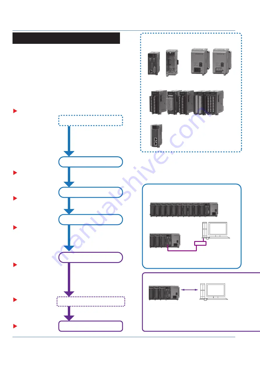
background image

8

IM 04L55B01-02EN


Operating Procedure

I/O modules

1

 (without the terminal covers)

Configure functions as necessary.

Turn on the power.

Prepare modules.

Check the modules.
Install the module base.
Link the modules.

Installation

Installing the Module Base

Checking the Modules

Linking the Module Base (Module)

Set the date and time.

Set signal inputs.

Reconfigure.

Set the measurement mode

Set the GM10 IP address.

Configure the GM settings.

Connect I/O signals and power.

Configure the system.

System Configuration

Multi Unit System

GX90EX linking position

Single Unit System

Configuration

Ethernet

USB

Bluetooth(/C8)

Main unit

Sub unit

Hub

Main unit

Sub unit

Sub unit

Sub unit

Indicates a reference.

“Wiring”

“Wiring”

“Basic Operations”

“Basic Operations”

Start recording/measuring.

URL: www.smartdacplus.com/manual/ja/

URL: www.smartdacplus.com/software/ja/

User’s Manual

(IM 04L55B01-01EN)

“Operating Procedure”

“Installation”

GM10

GX90EX

2

GX90EX

GM90MB

GM90PS

GM90MB

GM90MB

Module

Latch

GX90EX

Slide locks (vertical)

Lock

Unlock

Slide locks (vertical)

Screw (M3)

Connector

M3 screws for linking (included)

(top and bottom; 4)

Insert the module from the front of the GM90MB 

until a click is heard. Then, fasten the screw.

(Recommended tightening torque: 0.6 N•m)

GM supports both standalone operation and data acquisition 

using a PC.

Use a PC to configure the GM settings. To download the 

dedicated software application, you need to connect to the 

Internet.

If you need to set the time 

zone or DST (Daylight Saving 

Time) or both, do so before 

setting the date and time.

Download the following software applications.

S Standard Hardware Configurator

S Standard IP Address Configurator

See the list of electronic manuals on page 4 of IM 04L51B01-91EN, 

and download them if necessary.

Hardware Configurator is required for USB communication or 

Bluetooth communication (/C8 option).

A dedicated software application is not required for Ethernet 

connections.

(IP Address Configurator is used during installation.)

• Search for GM10s in the same network segment and list them.

• Set the IP address and other parameters of the GM10.

• GM settings can be configured offline from a Web browser.

IP Address Configurator Screen Example

Hardware Configurator Screen Example

Configuration of settings and real time monitoring 

are possible using a Web application.

A PC with Internet Explorer installed is required.

A system configured with a main unit connected to sub units.

Up to six sub units can be connected to a main unit. Each 

unit can connect up to six modules.

* There is a limitation on the number of channels based on 

the GM10 specifications (see IM 04L55B01-01EN).

A system configured with only a main unit.

The multi unit system support only cascaded connections.

If connected in a ring, none of the sub units will be identified.

Link the GX90EX to the left 

end on a main unit and next to 

the GM90PS on a sub unit.

Do not connect to avoid a 

ring connection.

For wall mounting, mount the GM90MB to 

the wall first, and then install the modules.

Protrusion 

(top and bottom; 4)

Guides (top and 

bottom; 4)

1. Check that the slide lock (vertical) is released (see below), align the four 

protrusions of the GM90MB to the guide, and push it in.

Removing a Module

1. Loosen the screw at the bottom section of the module.

2. While pressing down on the latch at the top of the module, 

pull the module out.

1  Some of the modules that can be used with the GM 

have firmware version conditions. See page 6.

2  The GX90EX is used to configure a multi unit 

system.

The firmware version of the GX90EX that can be 

used with the GM must be R1.02.01 or later.

2. After linking the module base, fix in place using the slide lock or the supplied screw.

(Recommended tightening torque: 0.4 to 0.5 N•m)

Push in

When carrying the unit, be sure that the 

modules are securely installed.

Lock: Slide toward the back of the module.
Unlock: Slide toward the front of the module.

You will hear a click both when 

locking and when unlocking.

Product user’s manuals can be downloaded from the following URL.

You can download the latest version of the software from the 

following URL.

Power supply connection:

Inlet or M4 screw terminal

PC

PC

Operations on the GM

Operations on the PC

Maximum connection distance 

between two units is 100 m.

Maximum connection distance 

between two units is 100 m.

A document number is 

indicated for manuals 

other than this manual.

Содержание SMARTDAC+ GM10

Страница 1: ...ail 14 Mounting on a Wall 14 Wiring 15 Precautions to Be Taken While Wiring 16 Removing andAttaching a Terminal Cover 16 Removing andAttaching a Terminal Block 16 Wiring Procedure 17 Internal dimensio...

Страница 2: ...out prior notice as a result of continuing improvements to the instrument s performance and functions Every effort has been made in the preparation of this manual to ensure the accuracy of its content...

Страница 3: ...ration or shock or pull out the card Data can become corrupt or permanently lost Only use Yokogawa SD cards Operation cannot be guaranteed with other brands of card When inserting the SD card into the...

Страница 4: ...iption GM90PS Power Supply Module for SMARTDAC GM Type 1 Always 1 Area N General Supply voltage 1 100 240V AC 2 12 28 V DC 1 Power supply connection D Power inlet with UL CSA cable F Power inlet with...

Страница 5: ...01 1 1GB Shunt resistor for M3 screw terminal 415940 1 250 0 1 415941 1 100 0 1 415942 1 10 0 1 Shunt resistor for clamp terminal 438920 1 250 0 1 438921 1 100 0 1 438922 1 10 0 1 GM10 Style Number Re...

Страница 6: ...system A unit consisting of a GM10 a GM90PS and a GX90EX Up to six I O modules can be connected to a unit Up to six sub units can be connected via the GX90EX Sub Unit multi unit system A unit consist...

Страница 7: ...not be detected GM10 1 If you want to use the DI of a GX90XD or GX90WD only a single module installed in the GM main unit can be used Do not link modules in a way that violates the specifications Doi...

Страница 8: ...or both do so before setting the date and time Download the following software applications SMARTDAC Standard Hardware Configurator SMARTDAC Standard IP Address Configurator See the list of electroni...

Страница 9: ...e IM 04L55B01 01EN The multi unit system support only cascaded connections If connected in a ring none of the sub units will be identified Link the GX90EX to the left end on a main unit and next to th...

Страница 10: ...e Expand reduce button 2 Click a No The corresponding GM10 is enabled 3 Click Network Config and set the items on the address setting screen For details on the settings see the IP Address Configurator...

Страница 11: ...er 1 and click the button under Channel set Channel number display The Group number 1 Channel set dialog box appears 3 Set AI channel 001 to 0010 to On and click OK The selected channels appear under...

Страница 12: ...unication Reconfiguration dialog box appears click OK The setup data of the connected GM will appear 3 Set the items 4 On the menu bar click the Setting tab and then Send Settings 5 When a Communicati...

Страница 13: ...hese kinds of circumstances wait for at least an hour before using the GM to acclimate it to the surrounding environment Well Ventilated Location To prevent overheating install the GM in a well ventil...

Страница 14: ...ront DIN rail DIN rail Rear of GM Click Check that all the latches are securely fastened to the DIN rail Removing from the DIN Rail 1 Lower the latch on the rear panel of the GM using a flat blade scr...

Страница 15: ...ed For all other signal cables use basic insulated cables dielectric strength of 1390 VAC To prevent electric shock attach the terminal cover after wiring and make sure not to touch the ter minals App...

Страница 16: ...n the thermocouple input take measures to stabilize the temperature at the input terminal Always use the terminal cover Do not use thick wires which may cause large heat dissipation we recommend a cro...

Страница 17: ...ection port and tighten the screw terminal Wiring to a GX90XA Analog Input Module Universal Low withstand voltage relay Electromagnetic relay Current mA type Terminal Diagram CH1 301 201 101 101 102 1...

Страница 18: ...A B B b A 5 DC current input with an external shunt resistor Be careful because the DI wiring is different between level and contact Terminal Arrangement M3 screw terminal CH No Term No Symbol Term N...

Страница 19: ...DI8 COM COM DI9 DI16 COM DI9 DI16 DI1 DI8 COM Wiring direction Wiring direction 11 19 11 19 21 29 21 29 Terminal Arrangement Term No Symbol Term No Symbol 21 DI9 11 DI1 22 DI10 12 DI2 23 DI11 13 DI3...

Страница 20: ...CH2 CH3 CH4 CH5 CH1 CH2 CH3 CH4 CH5 CH6 CH7 CH8 CH9 CH10 CH6 CH7 CH8 CH9 CH10 11 20 11 20 21 30 21 30 M3 screw terminal Clamp terminal Wiring direction Wiring direction Terminal Arrangement Term No S...

Страница 21: ...on Internal circuit Connecting to the RS 422 485 Connector C3 option Two wire system Four wire system Electric potential of the shield Shield FG SDB SG SDA RDB RDA Electric potential of the shield Shi...

Страница 22: ...rovide a power switch double pole type on the power supply line to separate the GM from the main power supply Use labels to indicate that this switch is for cutting off the power supply to the GM and...

Страница 23: ...Power On and Off If the power switch of GM GX60 systems under operation be turned on or off carelessly it may result the system down or injury Check the following points before turning on the power s...

Страница 24: ...L Red Lights during an error Setting Switches Dipswitches Use the dipswitches to set the unit number of the expansion module 10 Mbps fixed mode and operation mode master slave Dipswitch Settings Dipsw...

Отзывы: