24
IM 04L55B01-02EN
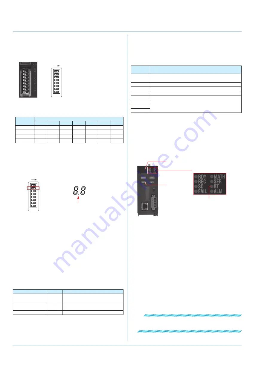
When the GX90EX is connected to the main unit, use master
I/O operation. Set dipswitch 8 of the GX90EX to ON (see the
figure below).
The unit number is set to 0.
1
2
3
4
5
6
7
8
ON
Setting switches
When the GX90EX is connected to a sub unit, set the
dipswitches as shown in the following table.
Unit Numbers and Dipswitch Settings
Dipswitch
Unit number
0*
1
2
3
4
5
6
4
OFF
OFF
OFF
OFF
OFF
OFF
OFF
3
OFF
OFF
OFF
OFF
ON
ON
ON
2
OFF
OFF
ON
ON
OFF
OFF
ON
1
OFF
ON
OFF
ON
OFF
ON
OFF
* The factory default setting. Unit number 0 is for the main
unit.
Fixing the Data Rate to 10 Mbps
To fix the data rate to 10 Mbps, set dipswitch 7 to ON.
7 segment LED for
10 Mbps fixed mode
Dot display
1
2
3
4
5
6
7
8
ON
Setting switches
7 segment LED
The 7 segment LED displays the unit number and operation
errors.
• Unit number indication
Displays the unit number (00 to 06).
• Operation error indication
Displays error codes. Ex (where x is a one digit number or
an alphabet letter) will blink.
For the error codes, see “Expansion Module Error Codes”
in the User’s Manual.
* If an “Fx” indication is displayed, servicing is necessary.
Contact your nearest YOKOGAWA dealer for repairs.
System Status Display LED
Three LEDs indicate the operating status of the GX90EX.
Status LED
Color
Description
RDY
Green
Lights during normal operation. Turns
off when during a failure.
MAIN
Green
Lights during master I/O expansion
operation.
FAIL
Red
Lights during an error.
Setting Switches (Dipswitches)
Use the dipswitches to set the unit number of the expansion
module, 10 Mbps fixed mode, and operation mode (master/
slave).
Dipswitch Settings
Dipswitch
Description
8
Switches between master I/O expansion and slave I/O
expansion modes
7
10Mbps/100Mbps
6
Always OFF (cannot be changed)
5
Always OFF (cannot be changed)
4
For unit numbers
3
2
1
Bluetooth Connection Procedure (/C8
option)
The following procedure applies when you are connecting for
the first time when the Bluetooth function is set to On (default
value).
1. Check that the GM10 BT LED is not lit.
USER1 key
Status display
7 segment LED×2
BT LED
(orange)
2. Hold down the GM10 USER1 key for at least 3 seconds.
The BT LED (orange) will turn on, and the GM will enter
the connection standby state.
3. Perform a pairing operation from the PC.
A 6-digit authentication code appears on the PC screen
and GM10’s 7 segment LED. Check that the authentication
codes match, and pair the devices. When pairing is
complete, a COM port will be assigned. You will need to
configure the COM port when connecting.
4. Connect to the GM from the PC.
When connecting for the first time, you need to enter the
password.
5. Enter
1234
(default value).
The BT LED will blink, and a connection will be established
with the GM.
Configure the GM using Hardware Configurator. For the
configuration procedure, see the S STANDARD
Hardware Configurator User’s Manual (IM 04L61B01-02EN).
Note
If the Bluetooth function is set to Off, the GM will not enter the
connection standby state even if you hold down the USER1
key for more than 3 seconds.


