General Instruction Manual
Product specification
Measuring principle and flow meter design
12 / 90
IM 01U10B00-00EN-R, 3rd edition, 2018-07-09
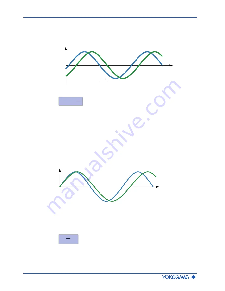
The small deformation overlying the fundamental vibration is recorded by means of pick-
offs (S1, S2) attached at suitable measuring tube locations. The resulting phase shift Δ
φ
between the output signals of pick-offs S1 and S2 is proportional to the mass flow. The
output signals generated are further processed in a transmitter.
Δφ
S1
S2
y
t
Fig. 3:
Phase shift between output signals of S1 and S2 pick-offs
Δ
φ
~
F
C
~
d
t
d
m
Δ
φ
Phase shift
m
Dynamic mass
t
Time
dm/dt
Mass flow
F
c
Coriolis force
Density
measurement
Using a driver and an electronic regulator, the measuring tubes are operated in their res-
onance frequency
ƒ
. This resonance frequency is a function of measuring tube geometry,
material properties and the mass of the fluid covibrating in the measuring tubes. Altering
the density and the attendant mass will alter the resonance frequency. The transmitter
measures the resonance frequency and calculates density from it according to the for-
mula below. Device-dependent constants are determined individually during calibration.
A
t
ƒ
2
ƒ
1
Fig. 4:
Resonance frequency of measuring tubes
A
Measuring tube displacement
ƒ
1
Resonance frequency with fluid 1
ƒ
2
Resonance frequency with fluid 2
ρ
=
+
ß
ƒ
2
α
ρ
Fluid density
ƒ
Resonance frequency of measuring tubes
α, β
Device-dependent constants


