《目次》 《索引》
TI 71M01D03-03
1st Edition : 2007.03.12-00
STEP 5-1.
Return to home position commanded by PLC
See also “6.11 Homing Using the PLC” in the TI
In STEP 5-1, it is guided how to return to home position using Z-pulse output
from <CN4> controller interface.
In this case, it is NOT necessary to connect proximity sensor to drive.
5-1.1 Generating Z-pulse and pulse interval
Generating method of Z-pulse and pulse interval depend on drive.
There are 2 methods for generating Z-pulse as below.
・Hardware: Z-pulse generated by optical encoder
・Software: Z-pulse generated by position signal processing by drive
Models
UD1A-□□□
UD1B-□□□
UR1A-□□□
UR1B-□□□
UR1E-□□□
UR5B-□□□
UR5E-□□□
Z-pulse
generated by
Hardware
Software
Z-pulse
ON duty
Approx. 10%
*1: excl. UD1B-004、UD1B-006
UD1C-□□□
Software
UR5C-□□□
Approx. 50%
UD1B-004/UD1B-006
(*1)
# Z-pluses
[1/rev]
100
60
200
124
150
68
78
124
52
124
Software
Approx. 12%
5-1.2 Accuracy of Z-pulse depending on velocity
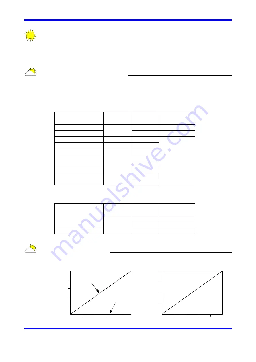
Accuracy of Z-pulse depends on velocity of motor. (see below figures)
Drive resolution
0.05[μm]
0.25[μm]
Z-pulse
interval
40960
8192
Z-pulse
ON duty
4096 - 16384
819 - 3276
0.5 [μm]
8192
819 - 3276
Z-pulse
generated by
Software
DYNASERV
LINEARSERV
0
0.01
0.02
0.03
0.04
0.05
10
15
20
25
5
0
ZE
RO
si
gna
l
ac
cur
acy
[arc-
sec]
Motor velocity
[rps]
In case of
hardware ZERO
In case of
software ZERO
DYNASERV
LINEARSERV
0
0.01
0.02
0.03
0.04
0.05
10
15
20
5
0
[μm]
Motor velocity
[m/s]
5-1
ZE
RO
si
gna
l
ac
cur
acy


