《目次》 《索引》
TI 71M01D03-03
1st Edition : 2007.03.12-00
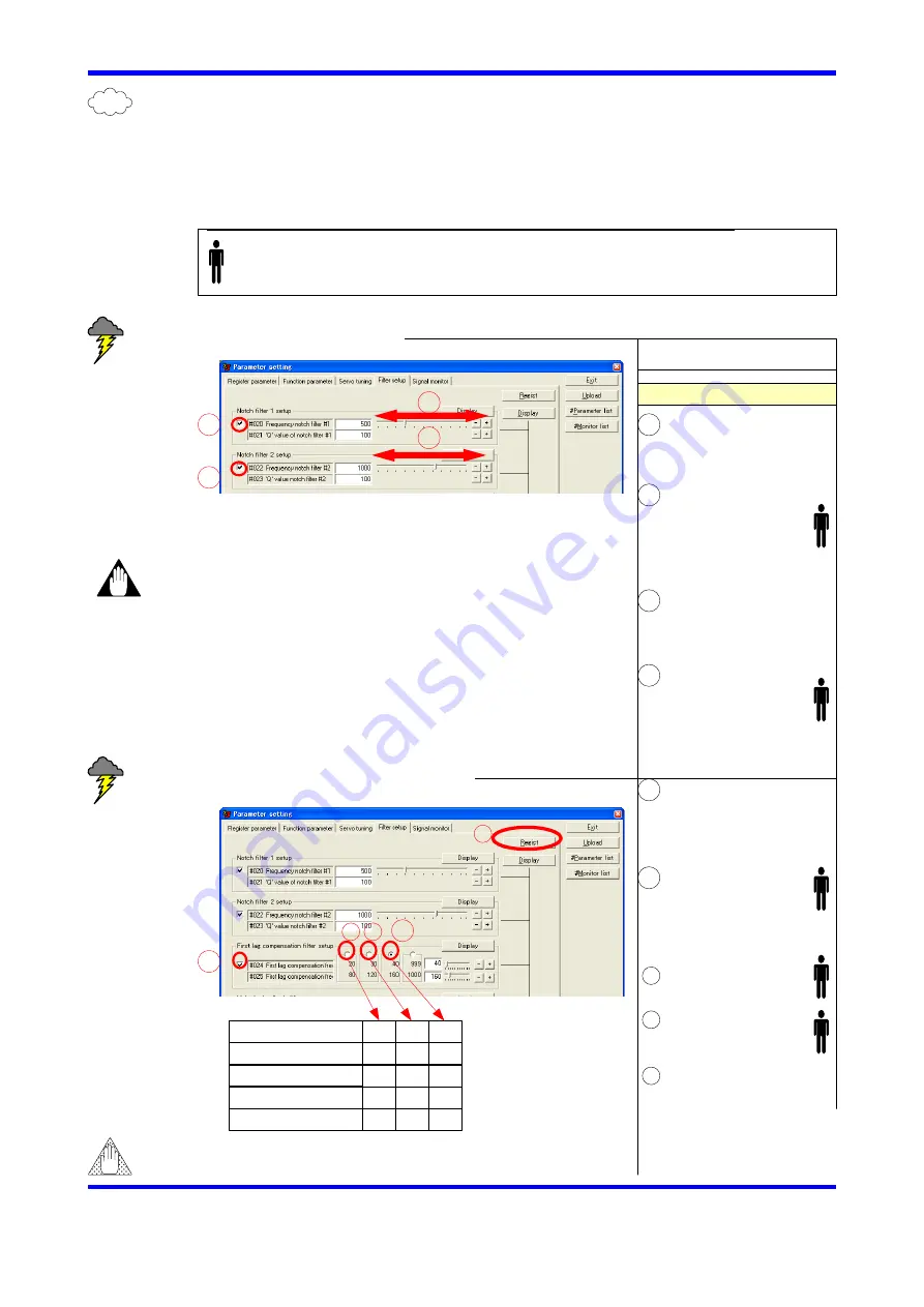
2.2 Filter setup
Filters are used when a resonance occurs, and it makes the peak value of
resonance lower. In many cases, filtering contributes to improve the servo
stiffness. On the other hand, it shifts the phase, and depending on the
circumstance, control system may become unstable. Please carefully use the
filters.
Carry out the following steps while the motor has resonance (noise).
2.3 Set notch filter
Operation Flow
Filter setup window
Check [Notch filter 1]
Shift cursor to the
right and left, and set
it at a point where the
noise becomes minimal.
<Human mark>
This symbol means that “register the setup and proceed to the STEP 3 at that step
if resonance is eliminated”. Proceed this flow if resonance is not eliminated.
Check notch filter 2.
2.4 Set the first lad compensation filter
Check [First lag
compensation filter]
Check [40/160].
Check [30/120].
Check [20/80].
Caution
First lag compensation filter’s response becomes
poor at lower frequency.
See also “7.2 Resonance Prevention” in the TI
4
5
4
5
6
7
It is recommended to use notch filters over 50Hz.
If it is used below 150Hz, a hunching may appear
due to the shifted phase.
6
7
Servo Stiffness
⑦
⑧
⑨
Over 3
2
1
Below 0
×
×
×
×
×
×
△
△
△
○
○
○
8
9
○:Possible to use
△:Carefully use
×:Impossible to use
8
9
Notch filter 1 becomes valid.
Seek resonance frequency.
Notch filter 2 becomes valid.
First lad compensation filter
becomes valid.
Band frequency for -3dB is
set at 40Hz, and max. damping
gain for +3dB becomes at
160Hz.
10
10
Click [Regist].
Register the filters setup
selected.
Warning
11
11
12
12
2-2
Shift cursor to the
right and left, and set
it at a point where the
noise becomes minimal.
Seek resonance frequency.


