6-16
166006-1CD
166006-1CD
6
Maintenance and Inspection
6.7 Main (Sweep) Axis Reduction Gear Unit (RV–320E–X)
RM2-755/1255SL
Positioner
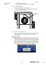
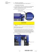
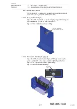
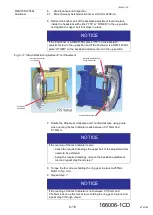
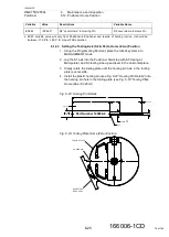
6. Retract the bottom bolt of the backlash adjustment tool and place
inside the headstock with either “755” or “OTHER” in the up position
and tighten the upper bolt till it stays in place.
Fig. 6
-
17: Attach Backlash Adjustment Tool Placement
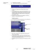
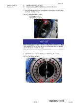
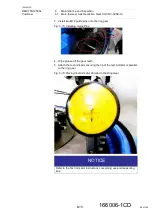
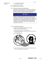
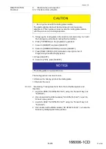
7. Rotate the Ring Gear clockwise and counterclockwise using guide
pins ensuring the test indicator reads between 0.110mm and
0.140mm.
8. Torque the four screws holding the ring gear in place to 255Nm.
.
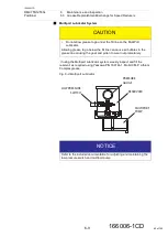
NOTICE
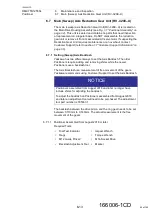
If the Positioner is a RM2-755SL place “755” on the backlash
adjustment tool in the up position and if the Positioner is a RM2-1255SL
place “OTHER” on the backlash adjustment tool in the up position.
Completely
Retract Bolt
Backlash Adjustment
Tool Number
↑
OTHER
Backlash Adjustment Tool
Positioner Number
Completely Retract Bolt
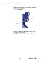
NOTICE
If the reading of the test indicator reads:
– above the required readings the upper bolt of the adjustment tool
needs to be extended.
– below the required readings, remove the backlash adjustment
tool and repeat
NOTICE
If the reading of the test indicator is not between 0.110mm and
0.140mm loosen up the four screws holding the ring gear in place and
67 of 145

