2-15
166006-1CD
166006-1CD
2
Installation
2.3 Positioner Installation
RM2-755/1255SL
Positioner
6. Check the elevation of the headstock to tailstock using a self leveling
laser.
7. Verify that the headstock is parallel to the tailstock by using the laser
from the headstock column machined plate making sure it hits the
same spot on the tailstock column.
2.3.4.3 Mounting the Positioner on the Floor
The floor should be strong enough to support the Positioner. Construct a
solid foundation with the appropriate thickness to withstand maximum
repulsion forces of the Positioner. When the thickness of the concrete floor
is 200mm or more, the Positioner can be fixed directly to the floor see
“Robotic Equipment Installation and Lagging Requirements”
and
Before mounting the Positioner on the floor, check the flatness, cracks,
etc. of the floor. If there are any cracks on the floor, they should be
repaired before installation. Any thickness less than 200mm is insufficient
for mounting, even if the floor is concrete. Use striker plates to prevent the
leveling bolts from embedding into the concrete.
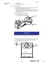
Head and tailstock column location should be checked for squareness
using a cross measuring method and using a level to determine that they
are parallel with each other vertically.
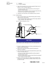
NOTICE
The Z-beam dowel pin is the recommended reference. The laser
should hit both dowel pins at the same elevation
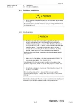
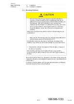
CAUTION
• Consult with a licensed civil engineer if the strength or integrity of
the floor is in question.
Not consulting a licensed civil engineer if there is any question
concerning the strength or integrity of the floor can cause equipment
damage.
38 of 145

