2-13
166006-1CD
166006-1CD
2
Installation
2.3 Positioner Installation
RM2-755/1255SL
Positioner
3. Adjust the leveling bolts so the top of the headstock frame is level in
both the “X” and “Y” direction within 0.5°.
• It is best to use three leveling bolts with the fourth leveling bolt
retracted to adjust the level.
• After the top of the headstock is level, the fourth leveling bolt can be
turned down to just contact the leveling bolt plate.
4. Lag the two outer most holes of the headstock column to the floor.
2.3.4.2 Setting Tailstock
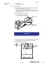
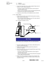
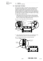
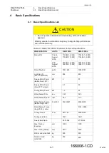
1. Place leveling bolt plates under each M20 leveling bolts so leveling
bolts do not rest on the concrete.
• There should be 6.35mm between the top of the leveling bolt plate
and the underside of the tailstock frame.
Fig. 2
-
8: Tailstock Installation on Floor.
2. Remove the shipping brackets (qty 2) that are attached between the
tailstock and the Z-beam frame.
3. Place a level on top of the tailstock (without the overhead rail
attachment if supplied).
4. Adjust the leveling bolts so the top of the tailstock frame is level in both
“X” and “Y” direction within 0.5°.
• It is best to use three leveling bolts with the fourth leveling bolt
retracted to adjust the level.
• After the top of the tailstock is level, turn down the fourth leveling bolt
to just contact the leveling bolt plate.
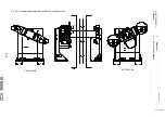
5. Measure the distance between the tailstock to the headstock at the
and ensure the distance between these points
are within 3.175mm.
SET HEIGHT OF TAILSTOCK HOUSING
BY ADJUSTING LEVELING BOLTS.
6.35mm
LEVELING BOLT PLATE
M20 LEVELING BOLT
NOTICE
This elevation is just a starting point, and is not a final requirement.
36 of 145

