


Advanced Operation
7.2.2 Setting/Adjusting Motor Constants
- 12
D
Settings
Setting
Name
10
Forward Torque Limit
11
Reverse Torque Limit
12
Regenerative Torque Limit
13
Torque reference (The input limits torque in both the forward and reverse directions during
speed control.)
15
Forward/Reverse Torque Limit (Limits torque in both the forward and reverse directions.)
D
The above table shows only those settings related to the torque limit function.
D
Set the analog input terminal’s signal level, gain, and bias to match the actual input signal.
D
The factory default settings for the input terminal’s signal level are as follows:
x
Terminal 16: 0 to +10 V (A 10 V input limits the torque to 100% of the motor’s rated torque.)
x
Terminal 14: 4 to 20 mA (A 20 mA input limits the torque to 100% of the motor’s rated torque.)
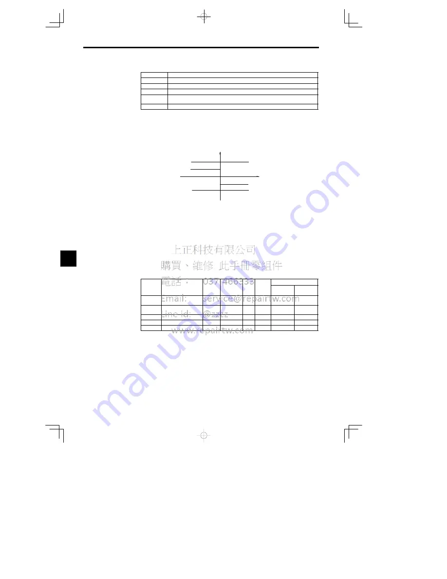
Figure 7.6 shows the relationship between the output torque and each torque limit.
Output torque
Forward
direction
Reverse
direction
Regenerative torque limit
Reverse torque limit
Motor speed
Reverse
Forward
Forward torque limit
Regenerative torque limit
Fig
7.6
Limiting Torque via Analog Inputs
D
When the forward torque limit has been set, the analog input signal acts as the limit value for torque
generated in the forward direction. The torque limit input is effective when torque is generated in the
forward direction even if the motor is operating in reverse (regenerative torque).
D
The torque limit is 100% of the motor’s rated torque when the analog input is at its maximum value
(10 V or 20 mA). To increase the torque limit above 100%, set the input terminal’s gain above 100%.
For example, a gain of 150.0% would result in a torque limit of 150% of the motor’s rated torque with
a 10 V or 20 mA analog input.
7.2.2 Setting/Adjusting Motor Constants
J
Adjusting the V/f Pattern: E1-04 to E1-06, E1--09, E1-13
D
Normally it isn’t necessary to adjust the V/f pattern with flux vector control. Adjust the V/f pattern
when you want to change the maximum output frequency, maximum voltage, base frequency, or mini-
mum output frequency settings.
User
Change
during
Setting
Factory
Valid Access Levels
User
Constant
Number
Name
during
Opera-
tion
Setting
Range
Unit
Factory
Setting
Open Loop
Vector
Flux Vector
E1-04
Max. output frequency
40.0 to
400.0
Hz
60.0
Q
Q
E1-05
Max. voltage
0.0
to
255.0
*1
VAC
200.0
*1
Q
Q
E1-06
Base frequency
0.0 to 400.0
Hz
60.0
Q
Q
E1-09
Min. output frequency
0.0 to 400.0
Hz
0.0
Q
A
E1-13
Base voltage
0.0 to 255.0
VAC
0.0
*2
Q
Q
* 1. These voltages are for the 200 V class; Double the voltage for 400 V class Inverters.
* 2. If E1-13 is set to 0.0, the same value as in E1-13 will be set for E1-05. It does not normally
need to be set separately.
Note 1.The default setting for E1-09 depends on the control method. The default settings shown
in the table are for flux vector control.
2. The three frequency settings must satisfy the following equation:
E1-04 (F
MAX
)
t
E1-06 (F
A
) > E1-09 (F
MIN
)
7