FAILURE DIAGNOSIS
1-168
TNV DI Service Manual
Method and Procedure of Failure Diagnosis
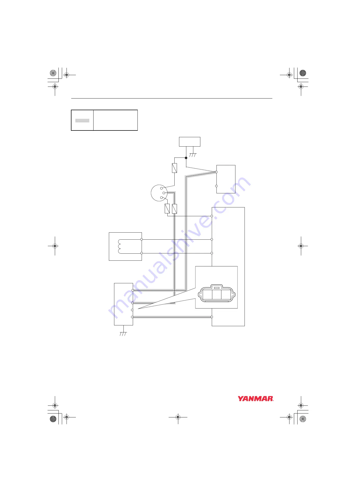
Wiring Diagram
*For the E-ECU Pin Layout, see [E-ECU Pin Layout Diagram] (P.1-134).
: Check points
E-ECU
Spare speed sensor (option)
(Alternator)
RENRPM
E10
Battery
+ −
B
S
Starter
Key switch
“ON” or “START”
Fuse
15A
Fuse
5A
CRK+
CRK-
B
A
Speed Sensor
NRPM-GND
E18
NRPM
E19
STARTSW
E08
B
L
IG
P
P01 B18 E10
Harness side coupler
(coupling face)
019610-00E
TNV_DI_SM_A4-Troubleshooting.book 168 ページ 2007年11月15日 木曜日 午後5時27分


