FAILURE DIAGNOSIS
1-206
TNV DI Service Manual
Method and Procedure of Failure Diagnosis
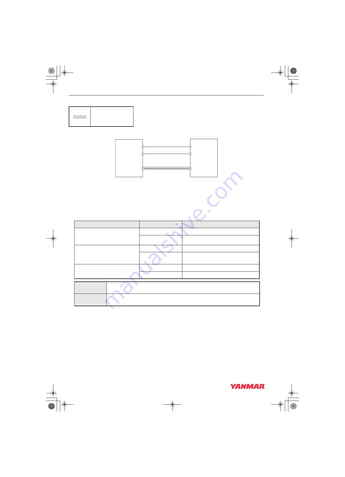
Wiring Diagram
* For the E-ECU Pin Layout, see [E-ECU Pin Layout Diagram] (P.1-134).
Work Description
1. Harness continuity check:
• Remove the immobilizer and E-ECU from the harness.
• Check the harness continuity using a circuit tester.
: Check points
019615-00E
APP-IP4
E17
Pulse communication
CANH
CANL
E40
E39
ECU
Immobilizer
CAN Communication
Terminal
Continuity
Status
Immobilizer pulse communication
line E17
[Between E-ECU and immobilizer]
Available
OK: normal
Unavailable
NG: harness disconnection
Between E17 and
E38/E43/E48(power supply line)
Unavailable
OK: normal
Available
NG: Harness short-circuited with power
supply
Between E17 and
E28/E45/E47(GND line)/GND
Unavailable
OK: normal
Available
NG: harness short-circuited with GND
NG
• Check if the harness is damaged, or if the wiring is correct.
• Replace the harness.
OK
• Check the immobilizer.
• Replace the E-ECU.
TNV_DI_SM_A4-Troubleshooting.book 206 ページ 2007年11月15日 木曜日 午後5時27分


