CHASSIS
3-23
NOTE:
• Be careful not to spill any brake fluid or allow
the brake master cylinder reservoir or brake
fluid reservoir to overflow.
• When bleeding the hydraulic brake system,
make sure there is always enough brake fluid
before applying the brake. Ignoring this pre-
caution could allow air to enter the hydraulic
brake system, considerably lengthening the
bleeding procedure.
• If bleeding is difficult, it may be necessary to let
the brake fluid settle for a few hours. Repeat
the bleeding procedure when the tiny bubbles
in the hose have disappeared.
2. Bleed:
• Hydraulic brake system
▼▼▼
▼
▼
▼▼▼
▼
▼
▼▼▼
▼
▼
▼▼▼
▼
▼
▼▼▼
▼
▼
▼▼▼
▼
▼▼▼
a. Fill the brake fluid reservoir to the proper level
with the recommended brake fluid.
b. Install the diaphragm (brake master cylinder
reservoir or brake fluid reservoir).
c. Connect a clear plastic hose “1” tightly to the
bleed screw “2”.
d. Place the other end of the hose into a con-
tainer.
e. Slowly apply the brake several times.
f. Fully pull the brake lever or fully press down
the brake pedal and hold it in position.
g. Loosen the bleed screw.
NOTE:
Loosening the bleed screw will release the pres-
sure and cause the brake lever to contact the
throttle grip or the brake pedal to fully extend.
h. Tighten the bleed screw and then release the
brake lever or brake pedal.
i. Repeat steps (e) to (h) until all of the air bub-
bles have disappeared from the brake fluid in
the plastic hose.
j. Tighten the bleed screw to specification.
k. Fill the brake fluid reservoir to the proper level
with the recommended brake fluid.
Refer to “CHECKING THE BRAKE FLUID
LEVEL” on page 3-20.
WARNING
EWA13110
After bleeding the hydraulic brake system,
check the brake operation.
▲▲▲
▲
▲
▲▲▲
▲
▲
▲▲▲
▲
▲
▲▲▲
▲
▲
▲▲▲
▲
▲
▲▲▲
▲
▲▲▲
3. Install:
• Rider seat
Refer to “GENERAL CHASSIS” on page 4-1.
EAS21380
ADJUSTING THE SHIFT PEDAL
NOTE:
The shift pedal position is determined by the in-
stalled shift rod length “a”.
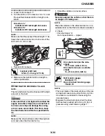
1. Measure:
• Installed shift rod length “a”
Incorrect
→
Adjust.
2. Adjust:
• Installed shift rod length
A. Front
B. Rear
1
2
A
2
1
B
T
R
.
Bleed screw (front brake caliper)
6 Nm (0.6 m·kg, 4.3 ft·lb)
Bleed screw (rear brake caliper)
6 Nm (0.6 m·kg, 4.3 ft·lb)
Installed shift rod length
312.0–316.0 mm (12.28–12.44 in)
a
Содержание XV19SW 2006
Страница 1: ...SERVICE MANUAL XV19SW C XV19W C XV19MW C XV19CTSW C XV19CTW C XV19CTMW C LIT 11616 20 40 1D7 28197 11...
Страница 6: ......
Страница 8: ......
Страница 24: ...SPECIAL TOOLS 1 15...
Страница 46: ...TIGHTENING TORQUES 2 21 Cylinder head tightening sequence 3 1 2 4 A B 3 1 2 4 A Front cylinder B Rear cylinder...
Страница 55: ...LUBRICATION POINTS AND LUBRICANT TYPES 2 30...
Страница 60: ...LUBRICATION SYSTEM CHART AND DIAGRAMS 2 35 D D B B D D C C A A B C C B 3 2 1 3 4 6 7 6 7 5...
Страница 62: ...LUBRICATION SYSTEM CHART AND DIAGRAMS 2 37 A A A A 1 3 2 4...
Страница 63: ...LUBRICATION SYSTEM CHART AND DIAGRAMS 2 38 1 Oil pipe 1 2 Oil pump 3 Oil strainer crankcase 4 Joint pipe...
Страница 64: ...LUBRICATION SYSTEM CHART AND DIAGRAMS 2 39 A 1 2 3 4...
Страница 66: ...LUBRICATION SYSTEM CHART AND DIAGRAMS 2 41 A A A 1 5 5 1 3 2 4 B B B B...
Страница 68: ...LUBRICATION SYSTEM CHART AND DIAGRAMS 2 43 1 2...
Страница 69: ...LUBRICATION SYSTEM CHART AND DIAGRAMS 2 44 1 Transfer gear oil pump 2 Middle driven shaft...
Страница 78: ...CABLE ROUTING 2 53...
Страница 86: ...CABLE ROUTING 2 61...
Страница 89: ......
Страница 122: ...ELECTRICAL SYSTEM 3 33 a b 1...
Страница 125: ......

