


GENERAL CHASSIS
4-2
ET1D71039
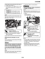
REMOVING THE WINDSHIELD
1. Remove:
• Windshield
▼▼▼
▼
▼
▼▼▼
▼
▼
▼▼▼
▼
▼
▼▼▼
▼
▼
▼▼▼
▼
▼
▼▼▼
▼
▼▼▼
a. Insert the key “1” into the windshield lock, turn
it clockwise and then remove the key.
b. Remove the windshield by pushing it forward,
and then pulling it upward as shown.
WARNING
EW1D71016
Be careful not to push the vehicle forward
when removing the windshield. The vehicle
could fall off the sidestand.
CAUTION:
EC1D71025
Securely hold the windshield to prevent it
from falling when removing.
▲▲▲
▲
▲
▲▲▲
▲
▲
▲▲▲
▲
▲
▲▲▲
▲
▲
▲▲▲
▲
▲
▲▲▲
▲
▲▲▲
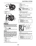
ET1D71045
ASSEMBLING THE WINDSHIELD
1. Install:
• Windshield lock “1”
NOTE:
Align the projection “a” on the lock “1” with the
slot “b” in the windshield bracket “2”.
ET1D71040
INSTALLING THE WINDSHIELD
1. Install:
• Right windshield holder bracket assembly “1”
NOTE:
Pass the throttle cables “2” between the front
fork and the right windshield holder bracket as-
sembly.
2. Install:
• Windshield
▼▼▼
▼
▼
▼▼▼
▼
▼
▼▼▼
▼
▼
▼▼▼
▼
▼
▼▼▼
▼
▼
▼▼▼
▼
▼▼▼
a. Fit the slot “a” in each windshield bracket (left
and right side) into its holder “b”.
NOTE:
Make sure that the throttle cables “1” are not
pinched.
b. Push the windshield backward until it snaps
into place.
2. Unlock.
2
1
a
1
2
b
2
1
b
a
1
Содержание XV19SW 2006
Страница 1: ...SERVICE MANUAL XV19SW C XV19W C XV19MW C XV19CTSW C XV19CTW C XV19CTMW C LIT 11616 20 40 1D7 28197 11...
Страница 6: ......
Страница 8: ......
Страница 24: ...SPECIAL TOOLS 1 15...
Страница 46: ...TIGHTENING TORQUES 2 21 Cylinder head tightening sequence 3 1 2 4 A B 3 1 2 4 A Front cylinder B Rear cylinder...
Страница 55: ...LUBRICATION POINTS AND LUBRICANT TYPES 2 30...
Страница 60: ...LUBRICATION SYSTEM CHART AND DIAGRAMS 2 35 D D B B D D C C A A B C C B 3 2 1 3 4 6 7 6 7 5...
Страница 62: ...LUBRICATION SYSTEM CHART AND DIAGRAMS 2 37 A A A A 1 3 2 4...
Страница 63: ...LUBRICATION SYSTEM CHART AND DIAGRAMS 2 38 1 Oil pipe 1 2 Oil pump 3 Oil strainer crankcase 4 Joint pipe...
Страница 64: ...LUBRICATION SYSTEM CHART AND DIAGRAMS 2 39 A 1 2 3 4...
Страница 66: ...LUBRICATION SYSTEM CHART AND DIAGRAMS 2 41 A A A 1 5 5 1 3 2 4 B B B B...
Страница 68: ...LUBRICATION SYSTEM CHART AND DIAGRAMS 2 43 1 2...
Страница 69: ...LUBRICATION SYSTEM CHART AND DIAGRAMS 2 44 1 Transfer gear oil pump 2 Middle driven shaft...
Страница 78: ...CABLE ROUTING 2 53...
Страница 86: ...CABLE ROUTING 2 61...
Страница 89: ......
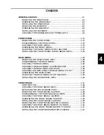
Страница 122: ...ELECTRICAL SYSTEM 3 33 a b 1...
Страница 125: ......