ELECTRICAL SYSTEM
3-32
b. Disconnect:
• Headlight coupler “1”
c. Detach:
• Headlight bulb holder “2”
d. Remove:
• Headlight bulb
WARNING
EWA13320
Since the headlight bulb gets extremely hot,
keep flammable products and your hands
away from the bulb until it has cooled down.
e. Install:
• Headlight bulb
Secure the new headlight bulb with the head-
light bulb holder.
CAUTION:
ECA13690
Avoid touching the glass part of the head-
light bulb to keep it free from oil, otherwise
the transparency of the glass, the life of the
bulb and the luminous flux will be adversely
affected. If the headlight bulb gets soiled,
thoroughly clean it with a cloth moistened
with alcohol or lacquer thinner.
f. Attach:
• Headlight bulb holder
g. Connect:
• Headlight coupler
h. Install:
• Headlight bulb cover
▲▲▲
▲
▲
▲▲▲
▲
▲
▲▲▲
▲
▲
▲▲▲
▲
▲
▲▲▲
▲
▲
▲▲▲
▲
▲▲▲
7. Install:
• Headlight assembly
8. Connect:
• Air temperature sensor coupler
9. Install:
• Headlight cover
10.Install:
• Windshield (For XV19CTS(C)/
XV19CT(C)/XV19CTM(C))
Refer to “GENERAL CHASSIS” on page 4-1.
EAS21810
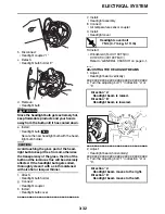
ADJUSTING THE HEADLIGHT BEAMS
1. Adjust:
• Headlight beam (vertically)
▼▼▼
▼
▼
▼▼▼
▼
▼
▼▼▼
▼
▼
▼▼▼
▼
▼
▼▼▼
▼
▼
▼▼▼
▼
▼▼▼
a. Turn the adjusting bolt “1” in direction “a” or
“b”.
▲▲▲
▲
▲
▲▲▲
▲
▲
▲▲▲
▲
▲
▲▲▲
▲
▲
▲▲▲
▲
▲
▲▲▲
▲
▲▲▲
2. Adjust:
• Headlight beam (horizontally)
▼▼▼
▼
▼
▼▼▼
▼
▼
▼▼▼
▼
▼
▼▼▼
▼
▼
▼▼▼
▼
▼
▼▼▼
▼
▼▼▼
a. Turn the adjusting bolt “1” in direction “a” or
“b”.
1
2
1
New
T
R
.
Headlight cover bolt
7 Nm (0.7 m·kg, 5.1 ft·lb)
Direction “a”
Headlight beam is raised.
Direction “b”
Headlight beam is lowered.
Direction “a”
Headlight beam moves to the right.
Direction “b”
Headlight beam moves to the left.
a
b
1
Содержание XV19SW 2006
Страница 1: ...SERVICE MANUAL XV19SW C XV19W C XV19MW C XV19CTSW C XV19CTW C XV19CTMW C LIT 11616 20 40 1D7 28197 11...
Страница 6: ......
Страница 8: ......
Страница 24: ...SPECIAL TOOLS 1 15...
Страница 46: ...TIGHTENING TORQUES 2 21 Cylinder head tightening sequence 3 1 2 4 A B 3 1 2 4 A Front cylinder B Rear cylinder...
Страница 55: ...LUBRICATION POINTS AND LUBRICANT TYPES 2 30...
Страница 60: ...LUBRICATION SYSTEM CHART AND DIAGRAMS 2 35 D D B B D D C C A A B C C B 3 2 1 3 4 6 7 6 7 5...
Страница 62: ...LUBRICATION SYSTEM CHART AND DIAGRAMS 2 37 A A A A 1 3 2 4...
Страница 63: ...LUBRICATION SYSTEM CHART AND DIAGRAMS 2 38 1 Oil pipe 1 2 Oil pump 3 Oil strainer crankcase 4 Joint pipe...
Страница 64: ...LUBRICATION SYSTEM CHART AND DIAGRAMS 2 39 A 1 2 3 4...
Страница 66: ...LUBRICATION SYSTEM CHART AND DIAGRAMS 2 41 A A A 1 5 5 1 3 2 4 B B B B...
Страница 68: ...LUBRICATION SYSTEM CHART AND DIAGRAMS 2 43 1 2...
Страница 69: ...LUBRICATION SYSTEM CHART AND DIAGRAMS 2 44 1 Transfer gear oil pump 2 Middle driven shaft...
Страница 78: ...CABLE ROUTING 2 53...
Страница 86: ...CABLE ROUTING 2 61...
Страница 89: ......
Страница 122: ...ELECTRICAL SYSTEM 3 33 a b 1...
Страница 125: ......


