CHASSIS
3-25
3. Remove:
• Muffler
Refer to “ENGINE REMOVAL” on page 5-1.
4. Adjust:
• Drive belt slack
▼▼▼
▼
▼
▼▼▼
▼
▼
▼▼▼
▼
▼
▼▼▼
▼
▼
▼▼▼
▼
▼
▼▼▼
▼
▼▼▼
NOTE:
Place the vehicle on a suitable stand so that the
rear wheel is elevated.
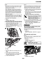
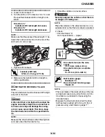
a. Loosen the wheel axle nut “1”.
b. Loosen both locknuts “2”.
c. Turn both adjusting bolts “3” in direction “a” or
“b” until the specified drive belt slack is ob-
tained.
NOTE:
Using the alignment marks on each side of the
swingarm, make sure that both belt pullers are in
the same position for proper wheel alignment.
d. Tighten the locknuts to specification.
e. Tighten the rear wheel axle nut to specifica-
tion.
▲▲▲
▲
▲
▲▲▲
▲
▲
▲▲▲
▲
▲
▲▲▲
▲
▲
▲▲▲
▲
▲
▲▲▲
▲
▲▲▲
5. Install:
• Muffler
Refer to “ENGINE REMOVAL” on page 5-1.
WARNING
EWA12800
Always use a new gasket.
EAS21510
CHECKING AND ADJUSTING THE
STEERING HEAD
1. Stand the vehicle on a level surface.
WARNING
EWA13120
Securely support the vehicle so that there is
no danger of it falling over.
NOTE:
Place the vehicle on a suitable stand so that the
front wheel is elevated.
2. Check:
• Steering head
Grasp the bottom of the front fork legs and
gently rock the front fork.
Binding/looseness
→
Adjust the steering
head.
Direction “a”
Drive belt is tightened.
Direction “b”
Drive belt is loosened.
1
1
2
3
a
b
T
R
.
Locknut (drive belt adjusting
bolt)
16 Nm (1.6 m·kg, 11 ft·lb)
T
R
.
Rear wheel axle nut
150 Nm (15.0 m·kg, 110 ft·lb)
Содержание XV19SW 2006
Страница 1: ...SERVICE MANUAL XV19SW C XV19W C XV19MW C XV19CTSW C XV19CTW C XV19CTMW C LIT 11616 20 40 1D7 28197 11...
Страница 6: ......
Страница 8: ......
Страница 24: ...SPECIAL TOOLS 1 15...
Страница 46: ...TIGHTENING TORQUES 2 21 Cylinder head tightening sequence 3 1 2 4 A B 3 1 2 4 A Front cylinder B Rear cylinder...
Страница 55: ...LUBRICATION POINTS AND LUBRICANT TYPES 2 30...
Страница 60: ...LUBRICATION SYSTEM CHART AND DIAGRAMS 2 35 D D B B D D C C A A B C C B 3 2 1 3 4 6 7 6 7 5...
Страница 62: ...LUBRICATION SYSTEM CHART AND DIAGRAMS 2 37 A A A A 1 3 2 4...
Страница 63: ...LUBRICATION SYSTEM CHART AND DIAGRAMS 2 38 1 Oil pipe 1 2 Oil pump 3 Oil strainer crankcase 4 Joint pipe...
Страница 64: ...LUBRICATION SYSTEM CHART AND DIAGRAMS 2 39 A 1 2 3 4...
Страница 66: ...LUBRICATION SYSTEM CHART AND DIAGRAMS 2 41 A A A 1 5 5 1 3 2 4 B B B B...
Страница 68: ...LUBRICATION SYSTEM CHART AND DIAGRAMS 2 43 1 2...
Страница 69: ...LUBRICATION SYSTEM CHART AND DIAGRAMS 2 44 1 Transfer gear oil pump 2 Middle driven shaft...
Страница 78: ...CABLE ROUTING 2 53...
Страница 86: ...CABLE ROUTING 2 61...
Страница 89: ......
Страница 122: ...ELECTRICAL SYSTEM 3 33 a b 1...
Страница 125: ......


