1-5
FEATURES
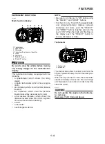
Tripmeter and tachometer modes
1. “SELECT” button
2. “RESET” button
Pushing the "SELECT" button switches the dis-
play between the tripmeter modes "TRIP 1" and
"TRIP 2" in the following order:
TRIP 1
6
TRIP 2
6
TRIP 1
When the fuel amount in the fuel tank decreas-
es to 6.7 L (1.77 US gal) (1.47 Imp.gal), the bot-
tom segment of the fuel meter will start flashing,
and the tripmeter display will automatically
change to the fuel reserve tripmeter mode “F-
TRIP” and start counting the distance traveled
from that point. In that case, pushing the "SE-
LECT" button switches the display between the
various tripmeter modes in the following order:
F-TRIP
6
TRIP 1
6
TRIP 2
6
F-TRIP
To reset a tripmeter, select it by pushing the "SE-
LECT" button, and then push the "RESET" button
for at least four seconds. If you do not reset the fu-
el reserve tripmeter manually, it will reset itself au-
tomatically and the display will return to the prior
mode after refueling and traveling 5 km (3 mi).
Clock mode
1. Clock
2. “SELECT” button
3. “RESET” button
NOTE:
The clock is displayed even when the key is
turned to "OFF".
To set the clock
1. Push the "SELECT" button for at least four
seconds.
2. When the hour digits start flashing, push the
"RESET" button to set the hours.
3. Push the "SELECT" button, and the minute
digits will start flashing.
4. Push the "RESET" button to set the minutes.
5. Push the "SELECT" button and then release
it to start the clock.
Fuel meter
1. Fuel meter
With the key in the "ON" position, the fuel meter
indicates the amount of fuel in the fuel tank.
When the key is turned to "ON", all of the display
segments of the fuel meter will appear one after
the other and then disappear in order to test the
electrical circuit. The display segments of the fu-
el meter disappear towards "E" (Empty) as the
fuel level decreases. When only one segment is
left near "E" (Empty), refuel as soon as possible.
Содержание XT660Z 2008
Страница 1: ...SERVICE MANUAL 2008 11D F8197 E0 XT660Z ...
Страница 8: ......
Страница 24: ......
Страница 44: ...2 20 TIGHTENING TORQUES Cylinder head tightening sequence 2 4 3 1 ...
Страница 52: ...2 28 COOLING SYSTEM DIAGRAMS EAS00033 COOLING SYSTEM DIAGRAMS 5VK 5VK00 A 4 A B 4 3 2 1 2 3 1 A A A ...
Страница 54: ...2 30 COOLING SYSTEM DIAGRAMS 1 2 3 4 5 6 7 9 10 11 12 5 8 11 A ...
Страница 57: ...2 33 LUBRICATION DIAGRAMS LUBRICATION DIAGRAMS 1 A A A A B B B A A B 3 2 2 4 1 1 5 5 ...
Страница 59: ...2 35 LUBRICATION DIAGRAMS A A A A 3 1 2 3 4 ...
Страница 60: ...2 36 LUBRICATION DIAGRAMS 1 Oil delivery pipe 2 2 Oil delivery pipe 1 3 Oil filter 4 Oil pump ...
Страница 61: ...2 37 LUBRICATION DIAGRAMS 1 7 2 3 4 5 6 A ...
Страница 63: ...2 39 LUBRICATION DIAGRAMS 1 6 5 4 3 2 ...
Страница 64: ...2 40 LUBRICATION DIAGRAMS 1 Camshaft 2 Oil delivery pipe 1 3 Oil filter 4 Main axle 5 Drive axle 6 Crankshaft ...
Страница 65: ...2 41 CABLE ROUTING CABLE ROUTING ...
Страница 67: ...2 43 CABLE ROUTING ...
Страница 69: ...2 45 CABLE ROUTING ...
Страница 71: ...2 47 CABLE ROUTING ...
Страница 73: ...2 49 CABLE ROUTING ...
Страница 75: ...2 51 CABLE ROUTING ...
Страница 77: ...2 53 CABLE ROUTING ...
Страница 79: ...2 55 CABLE ROUTING ...
Страница 81: ...2 57 CABLE ROUTING ...
Страница 83: ...2 59 CABLE ROUTING ...
Страница 84: ...2 60 CABLE ROUTING 1 Bolt union 2 Brake hose 3 Rear stop switch 4 Clamp hose A Add Loctite 243 ...
Страница 176: ...4 56 FRONT FORK WARNING Make sure the brake hoses are routed prop erly 1 2 3 ...
Страница 270: ......
Страница 284: ......
Страница 301: ...7 17 FUEL INJECTION SYSTEM WIRING DIAGRAM ...
Страница 324: ......
Страница 327: ...8 1 IGNITION SYSTEM EAS27090 IGNITION SYSTEM EAS27110 CIRCUIT DIAGRAM ...
Страница 331: ...8 5 ELECTRIC STARTING SYSTEM EAS27160 ELECTRIC STARTING SYSTEM EAS27170 CIRCUIT DIAGRAM ...
Страница 337: ...8 11 CHARGING SYSTEM EAS27200 CHARGING SYSTEM EAS27210 CIRCUIT DIAGRAM ...
Страница 338: ...8 12 CHARGING SYSTEM 2 A C magneto 5 Rectifier regulator 7 Battery 8 Main fuse ...
Страница 340: ...8 14 CHARGING SYSTEM ...
Страница 341: ...8 15 LIGHTING SYSTEM EAS27240 LIGHTING SYSTEM EAS27250 CIRCUIT DIAGRAM ...
Страница 345: ...8 19 SIGNALING SYSTEM EAS27270 SIGNALING SYSTEM EAS27280 CIRCUIT DIAGRAM ...
Страница 351: ...8 25 COOLING SYSTEM EAS00807 COOLING SYSTEM CIRCUIT DIAGRAM ...
Страница 354: ...8 28 COOLING SYSTEM ...
Страница 355: ...8 29 IMMOBILIZER SYSTEM ET5YU1002 IMMOBILIZER SYSTEM ET5YU1003 CIRCUIT DIAGRAM ...
Страница 364: ...8 38 IMMOBILIZER SYSTEM ...
Страница 365: ...8 39 ELECTRICAL COMPONENTS EAS27970 ELECTRICAL COMPONENTS ...
Страница 367: ...8 41 ELECTRICAL COMPONENTS ...
Страница 369: ...8 43 ELECTRICAL COMPONENTS EAS27980 CHECKING THE SWITCHES ...
Страница 388: ......
Страница 390: ......
Страница 396: ...COLOR CODE ...
Страница 397: ......
Страница 398: ...YAMAHA MOTOR ITALIA S P A ...
Страница 399: ...XT660Z 2008 WIRING DIAGRAM ...


