3-27
CHASSIS
WARNING
It is dangerous to ride with a worn-out tire.
When the tire tread reaches the wear limit,
replace the tire immediately.
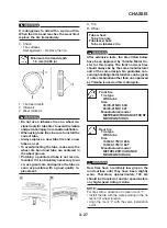
2. Check:
• Tire surfaces
Damage/wear
→
Replace the tire.
1. Tire tread depth
2. Sidewall
3. Wear indicator
WARNING
•
Do not use a tubeless tire on a wheel de-
signed only for tube tires to avoid tire failure
and personal injury from sudden deflation.
•
When using tube tires, be sure to install the
correct tube.
•
Always replace a new tube tire and a new
tube as a set.
•
To avoid pinching the tube, make sure the
wheel rim band and tube are centered in
the wheel groove.
•
Patching a punctured tube is not recom-
mended. If it is absolutely necessary to do
so, use great care and replace the tube as
soon as possible with a good quality re-
placement.
A. Tire
B. Wheel
WARNING
After extensive tests, the tires listed below
have been approved by Yamaha Motor Co.
Ltd. for this model. The front and rear tires
should always be by the same manufacturer
and of the same design. No guarantee con-
cerning handling characteristics can be given
if a tire combination other than one approved
by Yamaha is used on this motorcycle.
Tube wheel:
Tube tire only
Tubeless wheel:
Tube or tubeless tire
Minimum tire tread depth
1.6 mm (0.063 in)
Front tire
Tire type
With tube
Size
90/90-21M/C 54S
90/90-21M/C 54T
Manufacturer/model
METZELER/TOURANCE FRONT
MICHELIN/SIRAC
Rear tire
Tire type
With tube
Size
130/80-17M/C 65S
130/80-17M/C 65T
Manufacturer/model
METZELER/TOURANCE
MICHELIN/SIRAC A
WARNING
New tires have a relatively low grip on the
road surface until they have been slightly
worn. Therefore, approximately 100 km
should be traveled at normal speed before
any high-speed riding is done.
NOTE:
For tires with a direction of rotation mark “1”:
• Install the tire with the mark pointing in the di-
rection of wheel rotation.
• Align the mark “2” with the valve installation
point.
Содержание XT660Z 2008
Страница 1: ...SERVICE MANUAL 2008 11D F8197 E0 XT660Z ...
Страница 8: ......
Страница 24: ......
Страница 44: ...2 20 TIGHTENING TORQUES Cylinder head tightening sequence 2 4 3 1 ...
Страница 52: ...2 28 COOLING SYSTEM DIAGRAMS EAS00033 COOLING SYSTEM DIAGRAMS 5VK 5VK00 A 4 A B 4 3 2 1 2 3 1 A A A ...
Страница 54: ...2 30 COOLING SYSTEM DIAGRAMS 1 2 3 4 5 6 7 9 10 11 12 5 8 11 A ...
Страница 57: ...2 33 LUBRICATION DIAGRAMS LUBRICATION DIAGRAMS 1 A A A A B B B A A B 3 2 2 4 1 1 5 5 ...
Страница 59: ...2 35 LUBRICATION DIAGRAMS A A A A 3 1 2 3 4 ...
Страница 60: ...2 36 LUBRICATION DIAGRAMS 1 Oil delivery pipe 2 2 Oil delivery pipe 1 3 Oil filter 4 Oil pump ...
Страница 61: ...2 37 LUBRICATION DIAGRAMS 1 7 2 3 4 5 6 A ...
Страница 63: ...2 39 LUBRICATION DIAGRAMS 1 6 5 4 3 2 ...
Страница 64: ...2 40 LUBRICATION DIAGRAMS 1 Camshaft 2 Oil delivery pipe 1 3 Oil filter 4 Main axle 5 Drive axle 6 Crankshaft ...
Страница 65: ...2 41 CABLE ROUTING CABLE ROUTING ...
Страница 67: ...2 43 CABLE ROUTING ...
Страница 69: ...2 45 CABLE ROUTING ...
Страница 71: ...2 47 CABLE ROUTING ...
Страница 73: ...2 49 CABLE ROUTING ...
Страница 75: ...2 51 CABLE ROUTING ...
Страница 77: ...2 53 CABLE ROUTING ...
Страница 79: ...2 55 CABLE ROUTING ...
Страница 81: ...2 57 CABLE ROUTING ...
Страница 83: ...2 59 CABLE ROUTING ...
Страница 84: ...2 60 CABLE ROUTING 1 Bolt union 2 Brake hose 3 Rear stop switch 4 Clamp hose A Add Loctite 243 ...
Страница 176: ...4 56 FRONT FORK WARNING Make sure the brake hoses are routed prop erly 1 2 3 ...
Страница 270: ......
Страница 284: ......
Страница 301: ...7 17 FUEL INJECTION SYSTEM WIRING DIAGRAM ...
Страница 324: ......
Страница 327: ...8 1 IGNITION SYSTEM EAS27090 IGNITION SYSTEM EAS27110 CIRCUIT DIAGRAM ...
Страница 331: ...8 5 ELECTRIC STARTING SYSTEM EAS27160 ELECTRIC STARTING SYSTEM EAS27170 CIRCUIT DIAGRAM ...
Страница 337: ...8 11 CHARGING SYSTEM EAS27200 CHARGING SYSTEM EAS27210 CIRCUIT DIAGRAM ...
Страница 338: ...8 12 CHARGING SYSTEM 2 A C magneto 5 Rectifier regulator 7 Battery 8 Main fuse ...
Страница 340: ...8 14 CHARGING SYSTEM ...
Страница 341: ...8 15 LIGHTING SYSTEM EAS27240 LIGHTING SYSTEM EAS27250 CIRCUIT DIAGRAM ...
Страница 345: ...8 19 SIGNALING SYSTEM EAS27270 SIGNALING SYSTEM EAS27280 CIRCUIT DIAGRAM ...
Страница 351: ...8 25 COOLING SYSTEM EAS00807 COOLING SYSTEM CIRCUIT DIAGRAM ...
Страница 354: ...8 28 COOLING SYSTEM ...
Страница 355: ...8 29 IMMOBILIZER SYSTEM ET5YU1002 IMMOBILIZER SYSTEM ET5YU1003 CIRCUIT DIAGRAM ...
Страница 364: ...8 38 IMMOBILIZER SYSTEM ...
Страница 365: ...8 39 ELECTRICAL COMPONENTS EAS27970 ELECTRICAL COMPONENTS ...
Страница 367: ...8 41 ELECTRICAL COMPONENTS ...
Страница 369: ...8 43 ELECTRICAL COMPONENTS EAS27980 CHECKING THE SWITCHES ...
Страница 388: ......
Страница 390: ......
Страница 396: ...COLOR CODE ...
Страница 397: ......
Страница 398: ...YAMAHA MOTOR ITALIA S P A ...
Страница 399: ...XT660Z 2008 WIRING DIAGRAM ...


