7-31
FUEL INJECTION SYSTEM
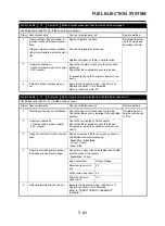
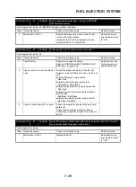
Fault code No.
14
Symptom
Intake air pressure sensor hose is disconnected or clogged.
Used diagnostic code No. 03 (intake air pressure sensor)
Order
Item/components
Check or maintenance job
Restore method
1
Disconnected, clogged, kinked, or
pinched intake air pressure sensor
hose
Repair or replace the hose.
Reinstated by start-
ing the engine and
operating it at idle.
Intake air pressure sensor malfunc-
tion at intermediate electrical poten-
tial
Check and repair the connection.
Replace the sensor if there is a malfunction.
2
Coupler connections
Intake air pressure sensor coupler
ECU coupler
Check the couplers for any pins that may have
pulled out.
Check that the couplers are securely locked.
If necessary, repair the coupler or securely con-
nect it.
3
Defective intake air pressure sen-
sor
Execute the diagnostic mode. (Code No. 03)
Replace the sensor if it is defective.
Refer to “Fault code No. 13”.
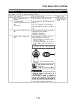
Fault code No.
15
Symptom
Open or short circuit is detected from the throttle position senor.
Used diagnostic code No. 01 (throttle position sensor)
Order
Item/components
Check or maintenance job
Restore method
1
Throttle position sensor installation
Check the sensor for looseness or pinching.
Check that the sensor is installed in the specified
position.
Reinstated by set-
ting the main switch
to “ON”.
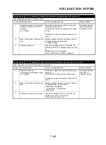
2
Coupler connections
Throttle position sensor coupler
ECU coupler
Check the connections of the couplers.
Check that the couplers are securely locked.
If necessary, repair the coupler or securely con-
nect it.
3
Open or short circuit in the wire har-
ness
Repair or replace if there is an open or short cir-
cuit between the wire harnesses.
Black/Blue - Black/Blue
Yell ow - Yel low
Blue - Blue
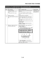
4
Check the throttle position sensor
lead open circuit output voltage.
Check for an open circuit and replace the throttle
position sensor, if necessary.
Black/Blue - Yellow
Open circuit item
Output voltage
Ground wire open cir-
cuit
5 V
Output wire open circuit 0 V
Power supply wire
open circuit
0 V
5
Defective throttle position sensor
Execute the diagnostic mode. (Code No. 01)
Replace the sensor if it is defective.
Refer to “THROTTLE BODY ASSEMBLY”
in chapter 7.
Содержание XT660Z 2008
Страница 1: ...SERVICE MANUAL 2008 11D F8197 E0 XT660Z ...
Страница 8: ......
Страница 24: ......
Страница 44: ...2 20 TIGHTENING TORQUES Cylinder head tightening sequence 2 4 3 1 ...
Страница 52: ...2 28 COOLING SYSTEM DIAGRAMS EAS00033 COOLING SYSTEM DIAGRAMS 5VK 5VK00 A 4 A B 4 3 2 1 2 3 1 A A A ...
Страница 54: ...2 30 COOLING SYSTEM DIAGRAMS 1 2 3 4 5 6 7 9 10 11 12 5 8 11 A ...
Страница 57: ...2 33 LUBRICATION DIAGRAMS LUBRICATION DIAGRAMS 1 A A A A B B B A A B 3 2 2 4 1 1 5 5 ...
Страница 59: ...2 35 LUBRICATION DIAGRAMS A A A A 3 1 2 3 4 ...
Страница 60: ...2 36 LUBRICATION DIAGRAMS 1 Oil delivery pipe 2 2 Oil delivery pipe 1 3 Oil filter 4 Oil pump ...
Страница 61: ...2 37 LUBRICATION DIAGRAMS 1 7 2 3 4 5 6 A ...
Страница 63: ...2 39 LUBRICATION DIAGRAMS 1 6 5 4 3 2 ...
Страница 64: ...2 40 LUBRICATION DIAGRAMS 1 Camshaft 2 Oil delivery pipe 1 3 Oil filter 4 Main axle 5 Drive axle 6 Crankshaft ...
Страница 65: ...2 41 CABLE ROUTING CABLE ROUTING ...
Страница 67: ...2 43 CABLE ROUTING ...
Страница 69: ...2 45 CABLE ROUTING ...
Страница 71: ...2 47 CABLE ROUTING ...
Страница 73: ...2 49 CABLE ROUTING ...
Страница 75: ...2 51 CABLE ROUTING ...
Страница 77: ...2 53 CABLE ROUTING ...
Страница 79: ...2 55 CABLE ROUTING ...
Страница 81: ...2 57 CABLE ROUTING ...
Страница 83: ...2 59 CABLE ROUTING ...
Страница 84: ...2 60 CABLE ROUTING 1 Bolt union 2 Brake hose 3 Rear stop switch 4 Clamp hose A Add Loctite 243 ...
Страница 176: ...4 56 FRONT FORK WARNING Make sure the brake hoses are routed prop erly 1 2 3 ...
Страница 270: ......
Страница 284: ......
Страница 301: ...7 17 FUEL INJECTION SYSTEM WIRING DIAGRAM ...
Страница 324: ......
Страница 327: ...8 1 IGNITION SYSTEM EAS27090 IGNITION SYSTEM EAS27110 CIRCUIT DIAGRAM ...
Страница 331: ...8 5 ELECTRIC STARTING SYSTEM EAS27160 ELECTRIC STARTING SYSTEM EAS27170 CIRCUIT DIAGRAM ...
Страница 337: ...8 11 CHARGING SYSTEM EAS27200 CHARGING SYSTEM EAS27210 CIRCUIT DIAGRAM ...
Страница 338: ...8 12 CHARGING SYSTEM 2 A C magneto 5 Rectifier regulator 7 Battery 8 Main fuse ...
Страница 340: ...8 14 CHARGING SYSTEM ...
Страница 341: ...8 15 LIGHTING SYSTEM EAS27240 LIGHTING SYSTEM EAS27250 CIRCUIT DIAGRAM ...
Страница 345: ...8 19 SIGNALING SYSTEM EAS27270 SIGNALING SYSTEM EAS27280 CIRCUIT DIAGRAM ...
Страница 351: ...8 25 COOLING SYSTEM EAS00807 COOLING SYSTEM CIRCUIT DIAGRAM ...
Страница 354: ...8 28 COOLING SYSTEM ...
Страница 355: ...8 29 IMMOBILIZER SYSTEM ET5YU1002 IMMOBILIZER SYSTEM ET5YU1003 CIRCUIT DIAGRAM ...
Страница 364: ...8 38 IMMOBILIZER SYSTEM ...
Страница 365: ...8 39 ELECTRICAL COMPONENTS EAS27970 ELECTRICAL COMPONENTS ...
Страница 367: ...8 41 ELECTRICAL COMPONENTS ...
Страница 369: ...8 43 ELECTRICAL COMPONENTS EAS27980 CHECKING THE SWITCHES ...
Страница 388: ......
Страница 390: ......
Страница 396: ...COLOR CODE ...
Страница 397: ......
Страница 398: ...YAMAHA MOTOR ITALIA S P A ...
Страница 399: ...XT660Z 2008 WIRING DIAGRAM ...


