7-20
FUEL INJECTION SYSTEM
EAS27380
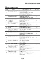
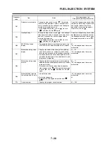
SELF-DIAGNOSTIC FUNCTION TABLE
If the ECU detects an abnormal signal from a sensor while the vehicle is being driven, the ECU illu-
minates the engine trouble warning light and provides the engine with alternate operating instruc-
tions that are appropriate for the type of malfunction.
When an abnormal signal is received from a sensor, the ECU processes the specified values that are
programmed for each sensor in order to provide the engine with alternate operating instructions that
enable the engine to continue to operate or stop operating, depending on the conditions.
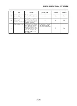
FAIL-SAFE ACTION TABLE
Self-diagnostic function
Fault
Item Symptom
Fail-safe
action
Startability
Driveability
code No.
12
Crankshaft position
No normal signals are
— No
No
sensor
received from the sensor.
Intake air pressure
Open or short circuit is
• Fixes the intake air pres-
13
sensor (open or short
detected.
sure to 101 kPa
Yes
Yes
circuit)
(760 mmHg, 29.9 inHg).
Intake air pressure
Intake air pressure sensor
• Fixes the intake air pres-
sensor
hose is clogged or discon-
sure to 101 kPa
14
nected, causing the constant
(760 mmHg, 29.9 inHg).
Yes
Yes
application of atmospheric
pressure to the sensor.
15
Throttle position sensor
Open or short circuit is
• Fixes the throttle position
Yes Yes
(open or short circuit)
detected.
sensor to fully open.
16
Throttle position
The throttle position sensor
• Fixes the throttle position
Yes Yes
sensor (stuck)
is detected stuck.
sensor to fully open.
Broken or discon-
Open circuit in the input line
19
nected blue/black
(blue/black) of the ECU is
—
No
No
lead of the ECU
detected.
21
Coolant temperature
Open or short circuit is
• Fixes the coolant tempe-
Yes Yes
sensor
detected.
rature to 80 °C (176 °F).
22
Intake air temperature
Open or short circuit is
• Fixes the intake air tem-
Yes Yes
sensor
detected.
perature to 20 °C (68 °F).
24
O
2
sensor
No normal signal is received
from the O
2
sensor.
— Yes
Yes
Lean angle cut-off
The motorcycle has
30
switch (latch up
overturned.
—
No
No
detected)
Open circuit is detected in
33
Faulty ignition
the primary lead of the
—
No
No
ignition coil.
Lean angle cut-off
Open or short circuit is
41
switch (open or
detected.
—
No
No
short circuit)
Speed sensor,
No normal signals are
• Fixes the gear to the top
neutral switch
received from the speed
gear.
42
sensor or an open or short
Yes
Yes
circuit is detected in the
neutral switch.
Fuel system voltage
The ECU is unable to
• Fixes the battery voltage
43
(monitor voltage)
monitor the battery voltage
to 12 V.
Yes
Yes
(open circuit in the wire to
the ECU).
Error in writing the
An error is detected while
44
amount of CO
reading or writing on
— Yes
Yes
adjustment on
EEPROM (CO adjustment
EEPROM
value).
Содержание XT660Z 2008
Страница 1: ...SERVICE MANUAL 2008 11D F8197 E0 XT660Z ...
Страница 8: ......
Страница 24: ......
Страница 44: ...2 20 TIGHTENING TORQUES Cylinder head tightening sequence 2 4 3 1 ...
Страница 52: ...2 28 COOLING SYSTEM DIAGRAMS EAS00033 COOLING SYSTEM DIAGRAMS 5VK 5VK00 A 4 A B 4 3 2 1 2 3 1 A A A ...
Страница 54: ...2 30 COOLING SYSTEM DIAGRAMS 1 2 3 4 5 6 7 9 10 11 12 5 8 11 A ...
Страница 57: ...2 33 LUBRICATION DIAGRAMS LUBRICATION DIAGRAMS 1 A A A A B B B A A B 3 2 2 4 1 1 5 5 ...
Страница 59: ...2 35 LUBRICATION DIAGRAMS A A A A 3 1 2 3 4 ...
Страница 60: ...2 36 LUBRICATION DIAGRAMS 1 Oil delivery pipe 2 2 Oil delivery pipe 1 3 Oil filter 4 Oil pump ...
Страница 61: ...2 37 LUBRICATION DIAGRAMS 1 7 2 3 4 5 6 A ...
Страница 63: ...2 39 LUBRICATION DIAGRAMS 1 6 5 4 3 2 ...
Страница 64: ...2 40 LUBRICATION DIAGRAMS 1 Camshaft 2 Oil delivery pipe 1 3 Oil filter 4 Main axle 5 Drive axle 6 Crankshaft ...
Страница 65: ...2 41 CABLE ROUTING CABLE ROUTING ...
Страница 67: ...2 43 CABLE ROUTING ...
Страница 69: ...2 45 CABLE ROUTING ...
Страница 71: ...2 47 CABLE ROUTING ...
Страница 73: ...2 49 CABLE ROUTING ...
Страница 75: ...2 51 CABLE ROUTING ...
Страница 77: ...2 53 CABLE ROUTING ...
Страница 79: ...2 55 CABLE ROUTING ...
Страница 81: ...2 57 CABLE ROUTING ...
Страница 83: ...2 59 CABLE ROUTING ...
Страница 84: ...2 60 CABLE ROUTING 1 Bolt union 2 Brake hose 3 Rear stop switch 4 Clamp hose A Add Loctite 243 ...
Страница 176: ...4 56 FRONT FORK WARNING Make sure the brake hoses are routed prop erly 1 2 3 ...
Страница 270: ......
Страница 284: ......
Страница 301: ...7 17 FUEL INJECTION SYSTEM WIRING DIAGRAM ...
Страница 324: ......
Страница 327: ...8 1 IGNITION SYSTEM EAS27090 IGNITION SYSTEM EAS27110 CIRCUIT DIAGRAM ...
Страница 331: ...8 5 ELECTRIC STARTING SYSTEM EAS27160 ELECTRIC STARTING SYSTEM EAS27170 CIRCUIT DIAGRAM ...
Страница 337: ...8 11 CHARGING SYSTEM EAS27200 CHARGING SYSTEM EAS27210 CIRCUIT DIAGRAM ...
Страница 338: ...8 12 CHARGING SYSTEM 2 A C magneto 5 Rectifier regulator 7 Battery 8 Main fuse ...
Страница 340: ...8 14 CHARGING SYSTEM ...
Страница 341: ...8 15 LIGHTING SYSTEM EAS27240 LIGHTING SYSTEM EAS27250 CIRCUIT DIAGRAM ...
Страница 345: ...8 19 SIGNALING SYSTEM EAS27270 SIGNALING SYSTEM EAS27280 CIRCUIT DIAGRAM ...
Страница 351: ...8 25 COOLING SYSTEM EAS00807 COOLING SYSTEM CIRCUIT DIAGRAM ...
Страница 354: ...8 28 COOLING SYSTEM ...
Страница 355: ...8 29 IMMOBILIZER SYSTEM ET5YU1002 IMMOBILIZER SYSTEM ET5YU1003 CIRCUIT DIAGRAM ...
Страница 364: ...8 38 IMMOBILIZER SYSTEM ...
Страница 365: ...8 39 ELECTRICAL COMPONENTS EAS27970 ELECTRICAL COMPONENTS ...
Страница 367: ...8 41 ELECTRICAL COMPONENTS ...
Страница 369: ...8 43 ELECTRICAL COMPONENTS EAS27980 CHECKING THE SWITCHES ...
Страница 388: ......
Страница 390: ......
Страница 396: ...COLOR CODE ...
Страница 397: ......
Страница 398: ...YAMAHA MOTOR ITALIA S P A ...
Страница 399: ...XT660Z 2008 WIRING DIAGRAM ...


