8-47
ELECTRICAL COMPONENTS
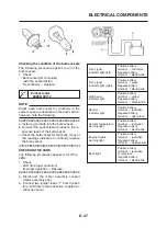
Checking the condition of the bulb sockets
The following procedure applies to all of the
bulb sockets.
1. Check:
• Bulb socket (for continuity)
(with the pocket tester)
No continuity
→
Replace.
NOTE:
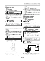
Check each bulb socket for continuity in the
same manner as described in the bulb section;
however, note the following.
a. Install a good bulb into the bulb socket.
b. Connect the pocket tester probes to the re-
spective leads of the bulb socket.
c. Check the bulb socket for continuity. If any of
the readings indicate no continuity, replace
the bulb socket.
CHECKING THE LEDS
The following procedures applies to all of the
LEDs.
1. Check:
• LED (for proper operation)
Improper operation
→
Replace.
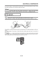
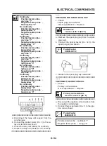
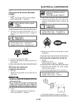
a. Disconnect the meter assembly coupler
(meter assembly end).
b. Connect two jumper leads “1” from the bat-
tery terminals to the respective coupler ter-
minal as shown.
Pocket tester
90890-03112
▼▼▼▼▼▼▼▼▼▼▼▼▼▼▼▼▼▼▼▼▼▼▼▼▼▼▼▼▼▼▼▼
▼▼▼▼▼▼▼▼▼▼▼▼▼▼▼▼▼▼▼▼▼▼▼▼▼▼▼▼▼▼▼▼
▼▼▼▼▼▼▼▼▼▼▼▼▼▼▼▼▼▼▼▼▼▼▼▼▼▼▼▼▼▼▼▼
Positive battery
Turn signal
terminal
→
chocolate
indicator light (left)
Negative battery
terminal
→
black/white
Positive battery
Turn signal
terminal
→
green
indicator light (right)
Negative battery
terminal
→
black/white
Positive battery
High beam
terminal
→
yellow
indicator light
Negative battery
terminal
→
black/white
Positive battery
Neutral
terminal
→
red/white
indicator light
Negative battery
terminal
→
light green
Positive battery
Coolant temperature
terminal
→
red/green
warning light
Negative battery
terminal
→
black/white
Positive battery
Engine trouble
terminal
→
red/white
warning light
Negative battery
terminal
→
white/yellow
Positive battery
terminal
→
red/white
Back light
or red/green
Negative battery
terminal
→
black/white
Содержание XT660Z 2008
Страница 1: ...SERVICE MANUAL 2008 11D F8197 E0 XT660Z ...
Страница 8: ......
Страница 24: ......
Страница 44: ...2 20 TIGHTENING TORQUES Cylinder head tightening sequence 2 4 3 1 ...
Страница 52: ...2 28 COOLING SYSTEM DIAGRAMS EAS00033 COOLING SYSTEM DIAGRAMS 5VK 5VK00 A 4 A B 4 3 2 1 2 3 1 A A A ...
Страница 54: ...2 30 COOLING SYSTEM DIAGRAMS 1 2 3 4 5 6 7 9 10 11 12 5 8 11 A ...
Страница 57: ...2 33 LUBRICATION DIAGRAMS LUBRICATION DIAGRAMS 1 A A A A B B B A A B 3 2 2 4 1 1 5 5 ...
Страница 59: ...2 35 LUBRICATION DIAGRAMS A A A A 3 1 2 3 4 ...
Страница 60: ...2 36 LUBRICATION DIAGRAMS 1 Oil delivery pipe 2 2 Oil delivery pipe 1 3 Oil filter 4 Oil pump ...
Страница 61: ...2 37 LUBRICATION DIAGRAMS 1 7 2 3 4 5 6 A ...
Страница 63: ...2 39 LUBRICATION DIAGRAMS 1 6 5 4 3 2 ...
Страница 64: ...2 40 LUBRICATION DIAGRAMS 1 Camshaft 2 Oil delivery pipe 1 3 Oil filter 4 Main axle 5 Drive axle 6 Crankshaft ...
Страница 65: ...2 41 CABLE ROUTING CABLE ROUTING ...
Страница 67: ...2 43 CABLE ROUTING ...
Страница 69: ...2 45 CABLE ROUTING ...
Страница 71: ...2 47 CABLE ROUTING ...
Страница 73: ...2 49 CABLE ROUTING ...
Страница 75: ...2 51 CABLE ROUTING ...
Страница 77: ...2 53 CABLE ROUTING ...
Страница 79: ...2 55 CABLE ROUTING ...
Страница 81: ...2 57 CABLE ROUTING ...
Страница 83: ...2 59 CABLE ROUTING ...
Страница 84: ...2 60 CABLE ROUTING 1 Bolt union 2 Brake hose 3 Rear stop switch 4 Clamp hose A Add Loctite 243 ...
Страница 176: ...4 56 FRONT FORK WARNING Make sure the brake hoses are routed prop erly 1 2 3 ...
Страница 270: ......
Страница 284: ......
Страница 301: ...7 17 FUEL INJECTION SYSTEM WIRING DIAGRAM ...
Страница 324: ......
Страница 327: ...8 1 IGNITION SYSTEM EAS27090 IGNITION SYSTEM EAS27110 CIRCUIT DIAGRAM ...
Страница 331: ...8 5 ELECTRIC STARTING SYSTEM EAS27160 ELECTRIC STARTING SYSTEM EAS27170 CIRCUIT DIAGRAM ...
Страница 337: ...8 11 CHARGING SYSTEM EAS27200 CHARGING SYSTEM EAS27210 CIRCUIT DIAGRAM ...
Страница 338: ...8 12 CHARGING SYSTEM 2 A C magneto 5 Rectifier regulator 7 Battery 8 Main fuse ...
Страница 340: ...8 14 CHARGING SYSTEM ...
Страница 341: ...8 15 LIGHTING SYSTEM EAS27240 LIGHTING SYSTEM EAS27250 CIRCUIT DIAGRAM ...
Страница 345: ...8 19 SIGNALING SYSTEM EAS27270 SIGNALING SYSTEM EAS27280 CIRCUIT DIAGRAM ...
Страница 351: ...8 25 COOLING SYSTEM EAS00807 COOLING SYSTEM CIRCUIT DIAGRAM ...
Страница 354: ...8 28 COOLING SYSTEM ...
Страница 355: ...8 29 IMMOBILIZER SYSTEM ET5YU1002 IMMOBILIZER SYSTEM ET5YU1003 CIRCUIT DIAGRAM ...
Страница 364: ...8 38 IMMOBILIZER SYSTEM ...
Страница 365: ...8 39 ELECTRICAL COMPONENTS EAS27970 ELECTRICAL COMPONENTS ...
Страница 367: ...8 41 ELECTRICAL COMPONENTS ...
Страница 369: ...8 43 ELECTRICAL COMPONENTS EAS27980 CHECKING THE SWITCHES ...
Страница 388: ......
Страница 390: ......
Страница 396: ...COLOR CODE ...
Страница 397: ......
Страница 398: ...YAMAHA MOTOR ITALIA S P A ...
Страница 399: ...XT660Z 2008 WIRING DIAGRAM ...


