background image

3 - 29

CHK

ADJ

CHECKING THE COOLANT LEVEL/CHECKING THE

COOLING SYSTEM/CHANGING THE COOLANT

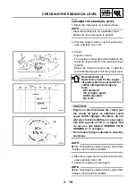
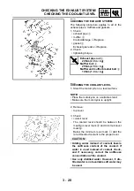
4. Start the engine, warm it up for several min-

utes, and then turn it off.

5. Check: 

• coolant level

NOTE:

Before checking the coolant level, wait a few
minutes until it settles. 

@

6. Install: 

• top cover

EAS00104 

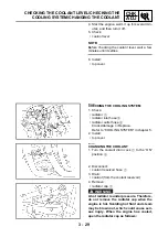
CHECKING THE COOLING SYSTEM
1. Check: 

• radiator 

1


• radiator inlet hose 

2


• radiator outlet hose 

3


Cracks/damage 

 Replace. 

Refer to “COOLING SYSTEM” in chapter 5.

2. Install: 

• top cover

EAS00105 

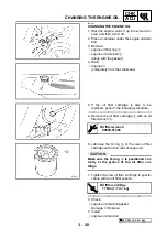
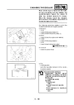
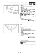
CHANGING THE COOLANT
1. Turn the coolant drain cock 

1

 to the “ON”

position 

2

.

2. Disconnect: 

• coolant reservoir hose 

1

3. Drain: 

• coolant (from the coolant reservoir)

4. Remove: 

• radiator cap 

2

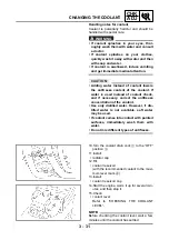
WARNING

A hot radiator is under pressure. Therefore,
do not remove the radiator cap when the
engine is hot. Scalding hot fluid and steam
may be blown out, which could cause seri-
ous injury. When the engine has cooled,
open the radiator cap as follows: 

Содержание VMX12 2001

Страница 1: ...VMX12 2001 3LRD AE1 SERVICEMANUAL ...

Страница 2: ......

Страница 3: ...MX12 2001 SERVICE MANUAL 2000 by Yamaha Motor Co Ltd First edition June 2000 All rights reserved Any reproduction or unauthorized use without the written permission of Yamaha Motor Co Ltd is expressly prohibited ...

Страница 4: ...els Modifications and significant changes in specifications or procedures will be forwarded to all authorized Yamaha deal ers and will appear in future editions of this manual where applicable NOTE Designs and specifications are subject to change without notice EAS00004 IMPORTANT MANUAL INFORMATION Particularly important information is distinguished in this manual by the following The Safety Alert...

Страница 5: ...of each page except in chapter 3 PERIODIC CHECKS AND ADJUSTMENTS where the sub section title s appears 3 Sub section titles appear in smaller print than the section title 4 To help identify parts and clarify procedure steps there are exploded diagrams at the start of each removal and disassembly section 5 Numbers are given in the order of the jobs in the exploded diagram A circled number indicates...

Страница 6: ...d B Lubricant C Special tool D Tightening torque E Wear limit clearance F Engine speed G Electrical data Symbols H to M in the exploded diagrams indicate the types of lubricants and lubrication points H Engine oil I Gear oil J Molybdenum disulfide oil K Wheel bearing grease L Lithium soap base grease M Molybdenum disulfide grease Symbols N to O in the exploded diagrams indicate the following N App...

Страница 7: ...TENTS GENERAL INFORMATION GEN INFO 1 SPECIFICATIONS SPEC 2 PERIODIC CHECKS AND ADJUSTMENTS CHK ADJ 3 ENGINE ENG 4 COOLING SYSTEM COOL 5 CARBURETION CARB 6 CHASSIS CHAS 7 ELECTRICAL SYSTEM ELEC 8 TROUBLESHOOTING TRBL SHTG 9 ...

Страница 8: ......

Страница 9: ...GEN INFO 1 ...

Страница 10: ...ICATION NUMBER 1 1 MODEL CODE 1 1 IMPORTANT INFORMATION 1 2 PREPARATION FOR REMOVAL AND DISASSEMBLY 1 2 REPLACEMENT PARTS 1 2 GASKETS OIL SEALS AND O RINGS 1 2 LOCK WASHERS PLATES AND COTTER PINS 1 3 BEARINGS AND OIL SEALS 1 3 CIRCLIPS 1 3 CHECKING THE CONNECTIONS 1 4 SPECIAL TOOLS 1 5 ...

Страница 11: ...GEN INFO ...

Страница 12: ...0017 VEHICLE IDENTIFICATION NUMBER The vehicle identification number 1 is stamped into the right side of the steering head pipe EAS00018 MODEL CODE The model code label 1 is affixed to the frame This information will be needed to order spare parts MOTORCYCLE IDENTIFICATION ...

Страница 13: ...an all of the parts and place them in trays in the order of dis assembly This will speed up assembly and allow for the correct installation of all parts 5 Keep all parts away from any source of fire EAS00021 REPLACEMENT PARTS Use only genuine Yamaha parts for all replacements Use oil and grease recom mended by Yamaha for all lubrication jobs Other brands may be similar in function and appearance b...

Страница 14: ...g oil seals lubricate the oil seal lips with a light coat of lithium soap base grease Oil bearings liberally when installing if appro priate 1 Oil seal CAUTION Do not spin the bearing with compressed air because this will damage the bearing surfaces 1 Bearing EAS00025 CIRCLIPS Before reassembly check all circlips carefully and replace damaged or distorted circlips Always replace piston pin clips a...

Страница 15: ... disconnect sev eral times 3 Check all connections Loose connection Connect properly NOTE If the pin 1 on the terminal is flattened bend it up 4 Connect lead coupler connector NOTE Make sure all connections are tight 5 Check continuity with the pocket tester NOTE If there is no continuity clean the terminals When checking the wire harness perform steps 1 to 3 As a quick remedy use a contact revita...

Страница 16: ...e guide remover 5 5 mm This tool is needed to remove and install the valve guide 90890 01196 Valve guide reamer 5 5 mm This tool is needed to rebore the new valve guide 90890 01229 Coupling gear middle shaft tool This tool is needed when removing or installing the coupling gear nut 90890 01230 Final gear backlash band This tool is needed when measuring final gear backlash 90890 01304 Piston pin pu...

Страница 17: ...ndle These tools are needed to loosen and tighten the damper rod holding bolt 90890 01403 Steering nut wrench This tool is needed to loosen and tighten the steering stem ring nut 90890 01426 Oil filter wrench This tool is needed to remove and install the oil filter 90890 01701 Sheave holder This tool is needed to hold the rotor when removing or installing the rotor bolt 90890 03017 Cylinder bore g...

Страница 18: ...or observing engine rpm 90890 03141 Timing light This tool is necessary for checking igni tion timing Gauge 90890 03153 Oil pressure adaptor B 90890 03124 Pressure gauge Oil pressure adaptor B These tools are needed to measure engine oil pressure 90890 04015 Valve guide installer 5 5 mm This tool is needed to install the valve guide Compressor 90890 04019 Attachment 90890 04114 Valve spring compre...

Страница 19: ...back lash adjustment 90890 04062 Universal joint holder This tool is needed when removing or installing the driven pinion gear nut 90890 04080 Middle gear backlash tool This tool is needed for the gear back lash adjustment 90890 04086 Clutch holding tool This tool is needed to hold the clutch when removing or installing the clutch boss nut 90890 04090 Damper spring compressor This tool is needed w...

Страница 20: ...on rings when installing the piston into the cylinder 90890 06754 Ignition checker 90890 85505 Yamaha Bond No 1215 This sealant bond is used on crank case mating surfaces etc 90890 01524 Ring gear fix bolt M14 This tool is used to measure the gear lash Tool No Tool name Function Illustration M14 P1 5 ...

Страница 21: ......

Страница 22: ...SPEC 2 ...

Страница 23: ...ICAL SPECIFICATIONS 2 14 CONVERSION TABLE 2 17 GENERAL TIGHTENING TORQUE SPECIFICATION 2 17 TIGHTENING TORQUES 2 18 ENGINE TIGHTENING TORQUES 2 18 CHASSIS TIGHTENING TORQUES 2 21 LUBRICATION POINTS AND LUBRICANT TYPES 2 23 ENGINE 2 23 CHASSIS 2 24 COOLING SYSTEM DIAGRAMS 2 25 OIL FLOW DIAGRAMS 2 27 CABLE ROUTING 2 31 ...

Страница 24: ...SPEC ...

Страница 25: ...l width 795 mm Overall height 1 160 mm Seat height 765 mm Wheelbase 1 590 mm Minimum ground clearance 145 mm Minimum turning radius 2 900 mm Weight Wet with oil and a full fuel tank 281 kg Dry without oil and fuel 262 kg Maximum load total of cargo rider passenger and accessories 209 kg GENERAL SPECIFICATIONS ...

Страница 26: ...0 kPa 14 5 kgf cm2 at 350 r min Fuel Recommended fuel Regular unleaded gasoline Fuel tank capacity Total including reserve 15 L Reserve only 3 L Engine oil Lubrication system Wet sump Recommended oil SAE 20W40SE or SAE 10W30SE Quantity Total amount 4 L Without oil filter cartridge replace ment 3 2 L With oil filter cartridge replacement 3 4 L Oil pressure hot 25 kPa at 1 000 r min 0 25 kgf cm2 at ...

Страница 27: ...iator capacity 3 05 L Radiator cap opening pressure 75 105 kPa 0 75 1 05 kgf cm2 Radiator core Width 363 8 mm Height 240 mm Depth 16 mm Coolant reservoir Capacity 0 3 L From low to full level 0 2 L Water pump Water pump type Single suction centrifugal pump Reduction ratio 31 21 1 476 Max impeller shaft tilt 0 15 mm Starting system type Electric starter Spark plugs Model manufacturer quantity DPR8E...

Страница 28: ...ter 24 967 24 980 mm Camshaft journal to camshaft cap clearance 0 020 0 054 mm Intake camshaft lobe dimensions Measurement A 36 25 36 35 mm 36 15 mm Measurement B 28 02 28 12 mm 27 92 mm Exhaust camshaft lobe dimensions Measurement A 36 25 36 35 mm 36 15 mm Measurement B 28 02 28 12 mm 27 92 mm Max camshaft runout 0 03 mm Item Standard Limit ...

Страница 29: ...0 9 1 1 mm 1 4 mm Exhaust 0 9 1 1 mm 1 4 mm Valve margin thickness D Intake 1 1 1 5 mm 0 7 mm Exhaust 1 1 1 5 mm 0 7 mm Valve stem diameter Intake 5 475 5 490 mm 5 445 mm Exhaust 5 460 5 475 mm 5 42 mm Valve guide inside diameter Intake 5 500 5 512 mm 5 55 mm Exhaust 5 500 5 512 mm 5 55 mm Valve stem to valve guide clear ance Intake 0 010 0 037 mm 0 08 mm Exhaust 0 025 0 052 mm 0 1 mm Valve stem r...

Страница 30: ... N 6 29 7 39 kgf Exhaust 61 7 72 5 N 6 29 7 39 kgf Spring tilt Intake 2 5 1 7 mm Exhaust 2 5 1 7 mm Winding direction top view Intake Counterclockwise Exhaust Counterclockwise Outer springs Free length Intake 41 1 mm 38 9 mm Exhaust 41 1 mm 38 9 mm Installed length valve closed Intake 33 8 mm Exhaust 33 8 mm Compressed spring force installed Intake 130 4 154 0 N 13 3 15 7 kgf Exhaust 130 4 154 0 N...

Страница 31: ...76 66 mm Compression ratio 10 5 1 Bore 75 967 76 016 mm Max taper 0 05 mm Max out of round 0 05 mm Pistons Piston to cylinder clearance 0 055 0 075 mm 0 15 mm Diameter D 75 905 75 955 mm Height H 6 2 mm Piston pin bore in the piston Diameter 19 004 19 015 mm Offset 0 mm Piston pins Outside diameter 18 991 19 000 mm Piston pin to piston pin bore clear ance 0 004 0 024 mm 0 072 mm Item Standard Limi...

Страница 32: ...2 5 3 1 mm End gap installed 0 2 0 8 mm Connecting rods Crankshaft pin to big end bearing clearance 0 021 0 039 mm Bearing color code 1 Blue 2 Black 3 Brown 4 Green 5 Yellow 6 Pink Crankshaft Width A 83 92 83 97 mm Width B 242 72 243 17 mm Max runout C 0 03 mm Big end side clearance D 0 320 0 924 mm Big end radial clearance 0 021 0 045 mm Crankshaft journal to crankshaft journal bearing clearance ...

Страница 33: ...n type Constant mesh 5 speed Primary reduction system Spur gear Primary reduction ratio 87 49 1 776 Secondary reduction system Shaft drive Secondary reduction ratio 21 27 33 10 2 567 Operation Left foot operation Gear ratios 1st gear 43 17 2 529 2nd gear 39 22 1 773 3rd gear 31 23 1 348 4th gear 28 26 1 077 5th gear 26 28 0 929 Max main axle runout 0 08 mm Max drive axle runout 0 08 mm Shifting me...

Страница 34: ...e 5DZ19 3 Needle jet Y 0 Pilot air jet 1 95 Pilot air jet 2 170 Pilot outlet 0 9 Pilot jet 42 5 Bypass 1 0 8 Bypass 2 0 8 Bypass 3 0 9 Pilot screw turns out 2 1 2 Valve seat size 1 5 Starter jet 1 45 Starter jet 2 0 8 Throttle valve size 125 Fuel level below the line on the vac uum chamber 15 17 mm Shaft drive Middle gear backlash 0 05 0 12 mm 0 3 mm Final gear backlash 0 1 0 2 mm 0 3 mm Item Stan...

Страница 35: ...el 100 mm Wheel runout Max radial wheel runout 1 mm Max lateral wheel runout 0 5 mm Front tire Tire type Tubeless Size 110 90V18 61V Model manufacturer ME33 METZELER Tire pressure cold 0 90 kg 225 kPa 2 25 kg cm2 2 25 bar 90 209 kg 225 kPa 2 25 kg cm2 2 25 bar High speed riding 225 kPa 2 25 kg cm2 2 25 bar Min tire tread depth 1 6 mm Rear tire Tire type Tubeless Size 150 90B 15M C 74V Model manufa...

Страница 36: ...pedal position 20 mm Recommended fluid DOT 4 Brake discs Diameter thickness 282 7 5 mm Min thickness 7 0 mm Max deflection 0 3 mm Brake pad lining thickness 5 1 mm 0 5 mm Master cylinder inside diameter 12 7 mm Caliper cylinder inside diameter 42 85 mm Front suspension Suspension type Telescopic fork Front fork type Coil air spring oil damper Front fork travel 140 mm Spring Free length 386 5 mm 38...

Страница 37: ...aring type Taper roller bearing Rear suspension Suspension type Swingarm Rear shock absorber assembly type Coil spring oil damper Rear shock absorber assembly travel 85 mm Spring Free length 245 5 mm 240 5 mm Installed length 217 4 mm Spring rate K1 19 1 N mm 1 95 kgf mm Spring stroke K1 0 50 mm Spring rate K2 26 5 N mm 2 7 kgf mm Spring stroke K2 50 85 mm Optional spring available No Swingarm Fre...

Страница 38: ...lug caps Material Resin Resistance 10 kΩ Charging system System type AC magneto Model manufacturer GP9415 KOKUSAN Nominal output 14 V 22 5 A at 5 000 r min Stator coil resistance 0 33 0 45 Ω Voltage regulator Regulator type Semiconductor short circuit Model SH662 12 No load regulated voltage 14 1 14 9 V Rectifier Model SH662 12 Rectifier capacity 18 A Withstand voltage 200 V Battery Battery type Y...

Страница 39: ...ignal relay Relay type Semi transistor Model manufacturer FB257H DENSO Self cancelling device built in Yes Turn signal blinking frequency 75 95 cycles min Wattage 21 W 2 3 4 W Oil level switch model manufacturer 1FK DENSO Fuel sender Model manufacturer 1FK NIPPON SEIKI Resistance 700 1 100 Ω at 25 C Sidestand relay Model 1RL 92 Coil resistance 72 88 Ω Fuel pump maximum amperage 1 2 A Fuel pump rel...

Страница 40: ...LECTRICAL SPECIFICATIONS Fuses amperage quantity Main fuse 30 A 1 Headlight fuse 15 A 1 Signaling system fuse 10 A 1 Ignition fuse 10 A 1 Radiator fan fuse 10 A 1 Reserve fuse 30 A 15 A 10 A 1 Item Standard Limit ...

Страница 41: ...s otherwise specified tightening torque specifications require clean dry threads Com ponents should be at room temperature A Width across flats B Thread diameter Ex METRIC MULTIPLIER IMPERIAL mm 0 03937 in 2 mm 0 03937 0 08 in METRIC TO IMPERIAL Tighten ing torque Metric unit Multiplier Imperial unit m kg m kg cm kg cm kg 7 233 86 794 0 0723 0 8679 ft lb in lb ft lb in lb Weight kg g 2 205 0 03527...

Страница 42: ...0 Thermostat assembly Bolt M6 2 10 1 0 Thermostat housing cover Bolt M6 2 7 0 7 Crankcase breather assembly Bolt M6 6 10 1 0 Crankcase breather cover Bolt M6 4 10 1 0 Radiator Bolt M6 4 7 0 7 Radiator side cover Screw M6 4 4 0 4 Coolant drain cock Screw M4 1 3 0 3 Radiator cap pipe Screw M6 3 7 0 7 Conduit Screw M6 3 7 0 7 Oil strainer housing Screw M6 3 7 0 7 Oil pump gear housing Screw M6 4 7 0 ...

Страница 43: ...il baffle plate Screw M6 4 7 0 7 LT Oil drain plug crankcase Bolt M8 1 38 3 8 Starter clutch Bolt M8 3 24 2 4 Clutch spring plate Bolt M6 6 8 0 8 Clutch boss Nut M20 1 70 7 0 Clutch release cylinder Bolt M6 2 12 1 2 Air bleed screw Screw M8 1 6 0 6 Clutch pipe Union bolt M10 1 25 2 5 Middle drive pinion gear Nut M44 1 110 11 0 LT Middle driven pinion gear Nut M16 1 90 9 0 LT Middle driven gear hou...

Страница 44: ...3 2 3 Stator coil Screw M6 3 7 0 7 LT Pickup coil Screw M6 4 7 0 7 LT Starter motor Bolt M6 2 10 1 0 Neutral switch Screw M5 3 4 0 4 Oil level switch Bolt M6 2 10 1 0 Thermo unit M10 1 15 1 5 Thermo switch M16 1 15 1 5 Crankcase tightening sequence Lower case Upper case With washer Part to be tightened Part name Thread size Q ty Tightening torque Remarks Nm m kgf ...

Страница 45: ...d down tube M10 45 4 5 Frame and rear cross bar M8 23 2 3 Swingarm pivot shaft left M25 100 10 0 Swingarm pivot shaft right M25 7 0 7 Swingarm pivot shaft locknut right M25 100 10 0 Rear shock absorber and frame M8 20 2 0 Rear shock absorber and swingarm M10 35 3 5 Rear shock absorber and final gear case M10 30 3 0 Swingarm and final gear case M10 42 4 2 Fuel sender and fuel tank M6 7 0 7 Side cov...

Страница 46: ...2 22 SPEC TIGHTENING TORQUES NOTE 1 First tighten the ring nut approximately 52 Nm 5 2 m kg by using the torque wrench then loosen the ring nut completely 2 Retighten the ring nut to specification ...

Страница 47: ...E Camshaft cam lobe journal E Timing chain tensioner E Valve stem IN EX M Valve stem end IN EX E Valve lifter E Water pump impeller shaft E Oil pump rotor inner outer housing E Oil strainer assembly E Idle gear surface E Starter idle gear E Starter idle gear shaft E Starter clutch outer roller E Push rod ball LS Pressure plate bearing E Transmission gear wheel pinion M Shift cam E Shift fork guide...

Страница 48: ...l seal right left LS Rear wheel oil seal LS Clutch hub fitting area LS Rear brake pedal shaft LS Shift pedal LS Sidestand sliding surface LS Centerstand sliding surface LS Tube guide throttle grip inner surface LS Brake lever pivot bolt contact surface LS Clutch lever pivot bolt contact surface LS Swingarm pivot shaft LS Swingarm pivot bearing M Swingarm pivot oil seal M Rear shock absorber bearin...

Страница 49: ...YSTEM DIAGRAMS COOLING SYSTEM DIAGRAMS 1 Radiator cap 2 Conduit 3 Radiator hose 4 Radiator 5 Thermostatic valve 6 Coolant drain cock 7 Water pump È To coolant reservoir tank É To thermostatic valve Ê To coolant drain cock ...

Страница 50: ...2 26 SPEC COOLING SYSTEM DIAGRAMS 1 Radiator cap 2 Conduit 3 Radiator hose 4 Radiator 5 Coolant drain cock 6 Thermostatic valve housing 7 Water pump È To thermostatic valve É To coolant drain cock ...

Страница 51: ...L FLOW DIAGRAMS OIL FLOW DIAGRAMS 1 Camshaft intake 2 Camshaft exhaust 3 Water pump impeller shaft 4 Water pump drive gear 5 Oil filter 6 Main gallery 7 Crankshaft 8 Oil strainer 9 Oil pump 0 Main axle A Drive axle ...

Страница 52: ...2 28 SPEC OIL FLOW DIAGRAMS 1 Camshaft 2 Main gallery 3 Crankshaft 4 Oil level switch ...

Страница 53: ...2 29 SPEC OIL FLOW DIAGRAMS 1 Oil pump 2 Oil strainer 3 Main axle 4 Drive axle 5 Middle driven pinion gear 6 Middle drive pinion gear ...

Страница 54: ...2 30 SPEC OIL FLOW DIAGRAMS 1 Crankshaft 2 Oil pipe 3 Oil filter ...

Страница 55: ...ad left 4 Speedometer cable 5 Wire harness 6 Speedometer light lead 7 Front flasher light lead right È Insert the wire harness speedometer light lead and front flasher light leads left and right through the hole in the housing at the back of the headlight É Pass the clutch hose through the guide ...

Страница 56: ...ch coupler 4 Ignition coil lead 5 Ground lead 6 Rear brake switch lead 7 Coolant reservoir tank breather hose 8 Battery breather hose 9 Fuel sender lead 0 Fuel sender coupler A Battery negative lead B Coolant breather hose C Conduit D Rear brake reservoir tank E Battery F Wire harness ...

Страница 57: ...ound lead outside the coolant reser voir tank breather hose Ë Pass the battery breather hose and coolant res ervoir tank breather hose through the guide Ì Pass the battery breather hose through the clamp Í Fasten the rear brake switch lead with a plastic locking tie Î Pass the wire harness through the clamp ...

Страница 58: ...dlebar switch lead left 3 Clutch hose clump 4 Throttle cable holder 5 Throttle cables 6 Fuse box 7 Ignitor unit 8 Ignition coil 9 Radiator fan lead coupler 0 Horn lead A Speedometer cable B Front brake hose C Fuel pump control unit D Relay unit ...

Страница 59: ...he throttle cable Ë Fasten the clutch hose with a plastic locking tie Ì Pass the horn lead through the clamp Í Pass the speedometer cable through the guide Î Pass the front brake hose through the clamp Ï Pass the front brake hose outside the speedom eter cable Ð Pass the clutch hose under the throttle cable guide Ñ Pass the throttle cables through the guide ...

Страница 60: ...e and AC generator lead with a plastic band to the frame guide É Fasten the oil level switch lead neutral switch lead ground lead sidestand switch lead overflow hose and AC generator lead with plastic band Ê Pass the oil level switch lead neutral switch lead ground lead and AC generator lead through the clamp Ë Pass the clutch hose and overflow hose through the guide Ì Fasten the oil level switch ...

Страница 61: ...l switch lead ground lead sidestand switch lead over flow hose and AC generator lead with a plastic band É Fasten the oil level switch lead neutral switch lead ground lead sidestand switch lead over flow hose and AC generator lead with a plastic band Ê Pass the clutch hose and overflow hose through the guide Ë Fasten the overflow hose with a plastic clamp Ì Pass the overflow hose through the guide...

Страница 62: ...38 SPEC CABLE ROUTING 1 Fuel pump 2 Fuel pipe 3 Fuel filter bracket 4 Fuel filter 5 Over flow hose 6 Filler cover 7 Filler cap 8 Battery band È Pass the fuel pipe and overflow hose through the hose holder ...

Страница 63: ...on coil lead coupler 8 Starter relay lead coupler 9 Fuel filter 0 Rubber boot A Rear flasher light lead left B Pick up coil lead coupler C Ground lead coupler D Side stand switch lead coupler E Rectifier regulator lead coupler F Oil level switch lead G Neutral switch lead H Battery positive lead I Main fuse J Starter motor lead K Fuel pump ...

Страница 64: ...e box M Meter lead coupler N Handlebar switch lead coupler È To the conduit É Fasten the wire harness with a plastic locking tie Ê Clamp the taillight lead and rear flasher light lead right Ë Clamp the rear flasher light lead left ...

Страница 65: ...CHK ADJ 3 ...

Страница 66: ...G THE SPARK PLUGS 3 15 CHECKING THE IGNITION TIMING 3 16 MEASURING THE COMPRESSION PRESSURE 3 17 CHECKING THE ENGINE OIL LEVEL 3 19 CHANGING THE ENGINE OIL 3 20 MEASURING THE ENGINE OIL PRESSURE 3 21 CHECKING THE CLUTCH FLUID LEVEL 3 23 BLEEDING THE HYDRAULIC CLUTCH SYSTEM 3 24 CLEANING THE AIR FILTER ELEMENT 3 25 CHECKING THE CARBURETOR JOINTS 3 26 CHECKING THE VACUUM HOSES 3 26 CHECKING THE FUEL...

Страница 67: ...NAL DRIVE OIL 3 39 CHECKING AND ADJUSTING THE STEERING HEAD 3 40 CHECKING THE FRONT FORK 3 42 ADJUSTING THE FRONT FORK LEGS 3 42 ADJUSTING THE REAR SHOCK ABSORBER ASSEMBLIES 3 43 CHECKING THE TIRES 3 45 CHECKING THE WHEELS 3 47 CHECKING AND LUBRICATING THE CABLES 3 48 LUBRICATING THE LEVERS AND PEDALS 3 48 LUBRICATING THE SIDESTAND 3 49 LUBRICATING THE CENTERSTAND 3 49 LUBRICATING THE REAR SUSPENS...

Страница 68: ...for cracks or damage 2 Fuel filter Check condition 3 Spark plugs Check condition Clean and regap Replace 4 Valves Check valve clearance Adjust 5 Air filter element Clean Replace 6 Battery Check electrolyte level and specific gravity Make sure that the breather hose is properly routed 7 Clutch Check operation fluid level and vehicle for fluid leakage See NOTE on page 3 2 8 Front brake Check operati...

Страница 69: ...heck operation Lubricate 18 Sidestand switch Check operation 19 Front fork Check operation and for oil leakage 20 Rear shock absorber assembly Check operation and shock absorbers for oil leak age 21 Carburetors Check engine idling speed synchronization and starter operation 22 Engine oil Change 23 Engine oil filter cartridge Replace 24 Cooling system Check coolant level and vehicle for coolant lea...

Страница 70: ...S Order Job Part Q ty Remarks Removing the seats and side covers Remove the parts in the order listed 1 Rider seat 1 2 Tool cover 1 3 Tool band 1 4 Tool kit 1 5 Passenger seat 1 6 Side covers left and right 2 For installation reverse the removal pro cedure ...

Страница 71: ...ER AND COVERS TOP COVER AND COVERS Order Job Part Q ty Remarks Removing the top cover and covers Remove the parts in the order listed 1 Top cover 1 2 Covers left and right 2 For installation reverse the removal pro cedure ...

Страница 72: ...ter case and electrical components board Remove the parts in the order listed Top cover and covers Refer to TOP COVER AND COVERS 1 Fuel pump control unit 1 Disconnect 2 Relay unit 1 Disconnect 3 Electrical components board 1 4 Air vent hose holder 2 5 Air filter case cover 1 6 Air filter 1 7 Air filter case 1 For installation reverse the removal pro cedure ...

Страница 73: ...stroke 1 Remove top cover covers left and right Refer to AIR FILTER CASE AND ELEC TRICAL COMPONENTS BOARD 2 Remove electrical components board 1 3 Disconnect all electrical component leads 4 Remove radiator side covers radiator bolt Refer to COOLING SYSTEM in chapter 5 NOTE It is not necessary to remove the radiator com pletely from the motorcycle 5 Disconnect spark plug caps 6 Remove air baffle p...

Страница 74: ...re the valve clearance with a thick ness gauge 3 NOTE If the valve clearance is incorrect record the measured reading Measure the valve clearance in the following sequence È Front d To measure the valve clearances of the other cylinders starting with cylinder 1 at TDC turn the crankshaft counterclockwise as specified in the following table É Degrees that the crankshaft is turned counter clockwise ...

Страница 75: ...ll screwdriver and a pair of twee zers Make a note of the position of each valve pad and valve pad number so they can be installed in the correct place e Select the proper valve pad from the follow ing table NOTE The thickness of each valve pad is marked in hundredths of millimeters on the side that touches the valve lifter not the camshaft Since valve pads of various sizes are origi nally install...

Страница 76: ...EARANCE INSTALLED PAD NUMBER 200 205 210 215 220 225 230 235 240 245 250 255 260 265 270 275 280 285 290 295 300 305 310 315 320 0 00 0 05 200 205 210 215 220 225 230 235 240 245 250 255 260 265 270 275 280 285 290 295 0 06 0 10 200 205 210 215 220 225 230 235 240 245 250 255 260 265 270 275 280 285 290 295 300 0 11 0 15 200 205 210 215 220 225 230 235 240 245 250 255 260 265 270 275 280 285 290 2...

Страница 77: ...on The valve clearance must be mea sured again and the above steps should be repeated if the measurement is still incorrect h Install the new valve pad with the numbered side facing down i Remove the tappet adjusting tool j Measure the valve clearance again k If the valve clearance is still out of specifica tion repeat all of the valve clearance adjust ment steps until the specified clearance is o...

Страница 78: ...2 Remove carburetor joint covers left and right vacuum plugs left and right vacuum hose Refer to CARBURETORS in chapter 6 3 Install vacuum gauge attachment into the bolt holes vacuum gauge 1 onto the vacuum gauge attachments engine tachometer 2 onto the spark plug lead of cylinder 1 4 Start the engine and let it warm up for sev eral minutes 5 Measure engine idling speed Out of specification Adjust...

Страница 79: ...Synchronize carburetor 2 to carburetor 3 by turning the synchronizing screw 3 in either direction until both gauges read the same NOTE The difference in vacuum pressure between two carburetors should not exceed 1 33 kPa 10 mm Hg 7 Measure engine idling speed Out of specification Adjust 8 Stop the engine and remove the measuring equipment 9 Adjust throttle cable free play Refer to ADJUSTING THE THR...

Страница 80: ... engine tachometer onto the spark plug lead of cylinder 1 3 Measure engine idling speed Out of specification Adjust Engine tachometer 90890 03113 Engine idling speed 950 1 050 r min 4 Adjust engine idling speed a Turn the throttle stop screw 1 in direction a or b until the specified engine idling speed is obtained 5 Adjust throttle cable free play Refer to ADJUSTING THE THROTTLE CABLE FREE PLAY Di...

Страница 81: ...the specified throttle cable free play is obtained c Tighten the locknuts NOTE If the specified throttle cable free play cannot be obtained on the carburetor side of the cable use the adjusting nut on the handlebar side Handlebar side a Loosen the locknut 3 b Turn the adjusting nut 4 in direction c or d until the specified throttle cable free play is obtained Throttle cable free play at the flange...

Страница 82: ...t spark plug cap 2 Remove spark plug CAUTION Before removing the spark plugs blow away any dirt accumulated in the spark plug wells with compressed air to prevent it from falling into the cylinders 3 Check spark plug type Incorrect Change 4 Check electrodes 1 Damage wear Replace the spark plug insulator 2 Abnormal color Replace the spark plug Normal color is medium to light tan 5 Clean spark plug ...

Страница 83: ...ng the ignition timing check the wiring connections of the entire ignition sys tem Make sure all connections are tight and free of corrosion 1 Remove timing plug 1 2 Attach timing light 1 engine tachometer 2 onto the spark plug lead of cylinder 1 3 Check ignition timing a Start the engine warm it up for several min utes and then let it run at the specified engine idling speed Timing light 90890 03...

Страница 84: ...E Insufficient compression pressure will result in a loss of performance 1 Measure valve clearance Out of specification Adjust Refer to ADJUSTING THE VALVE CLEARANCE 2 Start the engine warm it up for several min utes and then turn it off 3 Disconnect spark plug cap 4 Remove spark plug CAUTION Before removing the spark plugs use com pressed air to blow away any dirt accumu lated in the spark plug w...

Страница 85: ...surfaces and piston crown for carbon deposits Carbon deposits Eliminate d If the compression pressure is below the minimum specification squirt a few drops of oil into the cylinder and measure again Refer to the following table 7 Install spark plug 8 Connect spark plug cap Compression pressure at sea level Minimum 1 200 kPa 12 kg cm2 12 bar Standard 1 400 kPa 14 kg cm2 14 bar Maximum 1 600 kPa 16 ...

Страница 86: ...he wrong oil types or additives could cause clutch slippage Therefore do not add any chemical additives or use engine oils with a grade of CD c or higher and do not use oils labeled ENERGY CON SERVING II d or higher Do not allow foreign materials to enter the crankcase NOTE Before checking the engine oil level wait a few minutes until the oil has settled 4 Start the engine warm it up for several m...

Страница 87: ...lso to be replaced perform the following procedure a Remove the oil filter cartridge 1 with an oil filter wrench 2 Oil filter wrench 90890 01426 b Lubricate the O ring 3 of the new oil filter cartridge with a thin coat of engine oil CAUTION Make sure the O ring 3 is positioned cor rectly in the groove of the oil filter car tridge c Tighten the new oil filter cartridge to specifi cation with an oil...

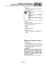
Страница 88: ... LEVEL Quantity Total amount 4 0 L Without oil filter cartridge replacement 3 2 L With oil filter cartridge replace ment 3 4 L EAS00077 MEASURING THE ENGINE OIL PRESSURE 1 Check engine oil level Below the minimum level mark Add the recommended engine oil to the proper level 2 Start the engine warm it up for several min utes and then turn it off CAUTION When the engine is cold the engine oil will h...

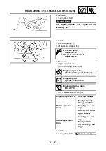
Страница 89: ...ication Adjust 6 Install main gallery bolt Pressure gauge 90890 03153 Oil pressure adapter B 90890 03124 Engine oil pressure 25 kPa 0 25 kg cm2 0 25 bar Engine speed Approx 1 000 r min Engine oil temperature 60 70 C Engine oil pressure Possible causes Below specifica tion Faulty oil pump Clogged oil filter Leaking oil pas sage Broken or dam aged oil seal Above specifica tion Leaking oil pas sage F...

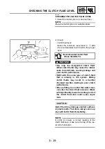
Страница 90: ...ce Refill with the same type of clutch fluid that is already in the system Mixing clutch fluids may result in a harmful chemical reaction leading to poor clutch performance When refilling be careful that water does not enter the clutch fluid reservoir Water will significantly lower the boiling point of the clutch fluid and could cause vapor lock CAUTION Clutch fluid may damage painted surfaces or ...

Страница 91: ...clutch system considerably length ening the bleeding procedure If bleeding is difficult it may be necessary to let the clutch fluid settle for a few hours Repeat the bleeding procedure when the tiny bubbles in the hose have disappeared 1 Bleed hydraulic clutch system a Add the recommended clutch fluid to the proper level b Install the clutch fluid reservoir diaphragm c Connect a clear plastic hose...

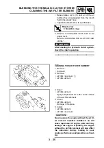
Страница 92: ...rew 6 Nm 0 6 m kg EAS00086 CLEANING THE AIR FILTER ELEMENT 1 Remove top cover 2 Remove air filter case cover 1 air filter element 3 Clean air filter element Apply compressed air to the outer surface of the air filter element 4 Check air filter element Damage Replace 5 Install air filter element air filter case cover CAUTION Never operate the engine without the air fil ter element installed Unfilte...

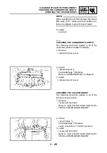
Страница 93: ... of the carburetor joints and intake manifolds 1 Remove carburetor joint covers 2 Check carburetor joint 1 Cracks damage Replace Refer to CARBURETORS in chapter 6 3 Install carburetor joint covers CHECKING THE VACUUM HOSES The following procedure applies to all of the fuel and vacuum hoses 1 Remove covers left and right Refer to AIR FILTER CASE AND ELEC TRICAL COMPONENTS BOARD 2 Check vacuum hose ...

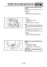
Страница 94: ...Replace fuel filter 2 Contaminants damage Replace NOTE Drain and flush the fuel tank if abrasive dam age to any components of the fuel line is evi dent The arrow mark on the fuel filter must point towards the fuel pump 3 as shown 3 Install rider seat Refer to SEATS AND SIDE COVERS EAS00098 CHECKING THE CRANKCASE BREATHER HOSE 1 Check crankcase breather hose 1 Cracks damage Replace Loose connection...

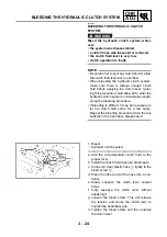
Страница 95: ...NG THE COOLANT LEVEL 1 Stand the motorcycle on a level surface NOTE Place the motorcycle on a suitable stand Make sure the motorcycle is upright 2 Remove top cover 3 Check coolant level The coolant level should be between the maximum level mark a and minimum level mark b Below the minimum level mark Add the recommended coolant to the proper level CAUTION Adding water instead of coolant lowers the ...

Страница 96: ...nlet hose 2 radiator outlet hose 3 Cracks damage Replace Refer to COOLING SYSTEM in chapter 5 2 Install top cover EAS00105 CHANGING THE COOLANT 1 Turn the coolant drain cock 1 to the ON position 2 2 Disconnect coolant reservoir hose 1 3 Drain coolant from the coolant reservoir 4 Remove radiator cap 2 WARNING A hot radiator is under pressure Therefore do not remove the radiator cap when the engine ...

Страница 97: ...ashers 5 Remove cover coolant drain plug engine 1 coolant drain bolt water pump 2 6 Drain coolant from the engine and radiator 7 Install coolant drain plug engine cover coolant drain bolt water pump 8 Connect coolant reservoir hose T R 43 Nm 4 3 m kg 9 Fill cooling system with the specified amount of the recom mended coolant Recommended antifreeze High quality ethylene glycol antifreeze containing...

Страница 98: ... coolant check and if necessary correct the antifreeze concentration of the coolant Use only distilled water However if dis tilled water is not available soft water may be used If coolant comes into contact with painted surfaces immediately wash them with water Do not mix different types of antifreeze 10 Turn the coolant drain cock 1 to the OFF position 2 11 Install radiator cap 12 Fill coolant re...

Страница 99: ... lever can indicate the presence of air in the brake system Before the vehicle is operated the air must be removed by bleeding the brake system Air in the brake system will consid erably reduce braking performance and could result in loss of control and possibly an accident Therefore check and if neces sary bleed the brake system CAUTION After adjusting the brake lever free play make sure there is...

Страница 100: ...ugh the hole d c Tighten the locknut 1 to specification WARNING A soft or spongy feeling in the brake pedal can indicate the presence of air in the brake system Before the vehicle is operated the air must be removed by bleeding the brake system Air in the brake system will consid erably reduce braking performance and could result in loss of control and possibly an accident Therefore check and if n...

Страница 101: ... may cause the rubber seals to deteriorate causing leakage and poor brake performance Refill with the same type of brake fluid that is already in the system Mixing brake fluids may result in a harmful chemical reaction leading to poor brake performance When refilling be careful that water does not enter the brake fluid reservoir Water will significantly lower the boiling point of the brake fluid a...

Страница 102: ...8 ADJUSTING THE REAR BRAKE LIGHT SWITCH NOTE The rear brake light switch is operated by movement of the brake pedal The rear brake light switch is properly adjusted when the brake light comes on just before the braking effect starts 1 Check rear brake light operation timing Incorrect Adjust 2 Adjust rear brake light operation timing a Hold the main body 1 of the rear brake light switch so that it ...

Страница 103: ...E SYSTEM WARNING Bleed the hydraulic brake system when ever the system is disassembled a brake hose is loosened disconnected or replaced the brake fluid level is very low brake operation is faulty NOTE Be careful not to spill any brake fluid or allow the brake master cylinder reservoir or brake fluid reservoir to overflow When bleeding the hydraulic brake system make sure there is always enough br...

Страница 104: ...brake pedal and hold it in posi tion g Loosen the bleed screw NOTE Loosening the bleed screw will release the pressure and cause the brake lever to contact the throttle grip or the brake pedal to fully extend h Tighten the bleed screw and then release the brake lever or brake pedal i Repeat steps e to h until all of the air bubbles have disappeared from the brake fluid in the plastic hose j Tighte...

Страница 105: ... locknuts 1 b Turn the adjusting bolt 2 in direction b or c to obtain the correct shift pedal position c Tighten both locknuts d Make sure the installed shift rod length is within specification Installed shift rod length 30 34 mm Direction b Installed shift rod length increases Direction c Installed shift rod length decreases EAS00144 CHECKING THE FINAL DRIVE OIL LEVEL 1 Stand the motorcycle on a ...

Страница 106: ...id gear oil graded GL 4 multi purpose SAE 80W90 hypoid gear oil T R 23 Nm 2 3 m kg EAS00145 CHANGING THE FINAL DRIVE OIL 1 Place a container under the final drive housing 2 Remove final drive housing oil filler bolt final drive housing oil drain bolt 1 Completely drain the final drive housing of its oil 3 Check final drive housing oil drain bolt gasket Damage Replace 4 Install final drive housing ...

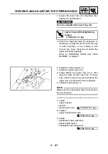
Страница 107: ...ly rock the front fork Binding looseness Adjust the steering head 3 Remove headlight body bracket bolt flasher light bracket handlebar holder assembly 4 Loosen upper bracket pinch bolts 1 5 Remove steering stem nut 2 washer upper bracket 3 6 Adjust steering head a Remove the lock washer 1 the upper ring nut 2 and the rubber washer 3 b Loosen the lower ring nut 4 and then tighten it to specificatio...

Страница 108: ...R Lower ring nut final tightening torque 3 0 Nm 0 3 m kg e Install the rubber washer 3 f Install the upper ring nut 2 g Finger tighten the upper ring nut 2 then align the slots of both ring nuts If neces sary hold the lower ring nut and tighten the upper ring nut until their slots are aligned h Install the lock washer 1 NOTE Make sure the lock washer tabs sit correctly in the ring nut slots 7 Inst...

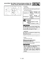
Страница 109: ...es and check if the front fork rebounds smoothly Rough movement Repair Refer to FRONT FORK in chapter 7 ADJUSTING THE FRONT FORK LEGS The following procedure applies to both of the front fork legs WARNING Always adjust both front fork legs evenly Uneven adjustment can result in poor handling and loss of stability Securely support the motorcycle so that there is no danger of it falling over Spring ...

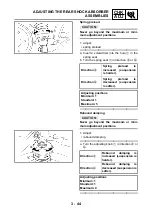
Страница 110: ...ying air Spring preload is increased suspension is harder Releasing air Spring preload is decreased suspension is softer Air pressure Standard 40 kPa 0 4 kg cm2 0 4 bar Maximum 100 kPa 1 0 kg cm2 1 0 bar 4 Install front fork air valve cap EAS00161 ADJUSTING THE REAR SHOCK ABSORBER ASSEMBLIES The following procedure applies to both of the rear shock absorber assemblies WARNING Securely support the ...

Страница 111: ...AUTION Never go beyond the maximum or mini mum adjustment positions 1 Adjust rebound damping a Turn the adjusting knob 1 in direction a or b Direction a Spring preload is increased suspension is harder Direction b Spring preload is decreased suspension is softer Adjusting positions Minimum 1 Standard 1 Maximum 5 Direction a Rebound damping is increased suspension is harder Direction b Rebound damp...

Страница 112: ...cipated riding speed Operation of an overloaded motorcycle could cause tire damage an accident or an injury NEVER OVERLOAD THE MOTORCYCLE total of cargo rider passenger and accessories WARNING It is dangerous to ride with a worn out tire When the tire tread reaches the wear limit replace the tire immediately Basic weight with oil and a full fuel tank 281 kg Maximum load 209 kg Cold tire pressure F...

Страница 113: ...in the wheel groove Patching a punctured tube is not recom mended If it is absolutely necessary to do so use great care and replace the tube as soon as possible with a good quality replacement È Tire É Wheel After extensive tests the tires listed below have been approved by Yamaha Motor Co Ltd for this model The front and rear tires should always be by the same manufacturer and of the same design ...

Страница 114: ...nut 2 to specification NOTE For tires with a direction of rotation mark 3 Install the tire with the mark pointing in the direction of wheel rotation Align the mark 4 with the valve installation point EAS00168 CHECKING THE WHEELS The following procedure applies to both of the wheels 1 Check wheel Damage out of round Replace WARNING Never attempt to make any repairs to the wheel Manufacturer Model S...

Страница 115: ...to corrode and interfere with its movement Replace damaged cable sheaths and cables as soon as possible 1 Check cable sheath Damage Replace 2 Check cable operation Rough movement Lubricate NOTE Hold the cable end upright and pour a few drops of lubricant into the cable sheath or use a suitable lubricating device Recommended lubricant Engine oil or a suitable cable lubricant EAS00171 LUBRICATING TH...

Страница 116: ...the sidestand Recommended lubricant Lithium soap base grease EAS00173 LUBRICATING THE CENTERSTAND Lubricate the pivoting point and metal to metal moving parts of the centerstand Recommended lubricant Lithium soap base grease EAS00174 LUBRICATING THE REAR SUSPENSION Lubricate the pivoting point and metal to metal moving parts of the rear suspension Recommended lubricant Molybdenum disulfide grease ...

Страница 117: ... SMOKE when charging or han dling batteries KEEP BATTERIES AND ELECTROLYTE OUT OF REACH OF CHILDREN Avoid bodily contact with electrolyte as it can cause severe burns or permanent eye injury FIRST AID IN CASE OF BODILY CONTACT EXTERNAL Skin Wash with water Eyes Flush with water for 15 minutes and get immediate medical attention INTERNAL Drink large quantities of water or milk fol lowed with milk o...

Страница 118: ...he battery breather hose and battery vent are free of obstructions To ensure maximum performance always charge a new battery before using it Do not use a high rate battery charger They force a high amperage current into the battery quickly and can cause battery overheating and battery plate damage If it is impossible to regulate the charging current on the battery charger be careful not to overcha...

Страница 119: ...ime during the charging process disconnect the battery charger and let the battery cool before reconnecting it Hot batteries can explode NOTE Replace the battery whenever battery voltage does not rise to specification or bubbles fail to rise during charging sulphation of one or more battery cells occurs as indicated by the battery plates turning white or material accumulating in the bottom of the ...

Страница 120: ...cle and its finish may be damaged Make sure the battery breather hose is properly routed away from the drive chain and from below the swingarm 11 Check battery terminals Dirt Clean with a wire brush Loose connection Connect properly 12 Connect battery leads to the battery terminals CAUTION First connect the positive battery lead 1 and then the negative lead 2 13 Lubricate battery terminals 14 Inst...

Страница 121: ...D SIDE COVERS 2 Check continuity a Connect the pocket tester to the fuse and check the continuity NOTE Set the pocket tester selector to Ω 1 b If the pocket tester indicates replace the fuse Pocket tester 90890 03112 3 Replace blown fuse a Set the main switch to OFF b Install a new fuse of the correct amperage c Set on the switches to verify if the electrical circuit is operational d If the fuse i...

Страница 122: ...trical system cause the lighting and ignition systems to malfunction and could possibly cause a fire 4 Install rider seat Refer to SEATS AND SIDE COVERS Items Amperage rating Q ty Main fuse 30 A 1 Headlight fuse 15 A 1 Signaling system fuse 10 A 1 Ignition fuse 10 A 1 Radiator fan motor fuse 10 A 1 Reserve fuse 30 A 1 Reserve fuse 15 A 1 Reserve fuse 10 A 1 EAS00182 REPLACING THE HEADLIGHT BULB 1 ...

Страница 123: ...l headlight bulb Secure the new headlight bulb with the headlight bulb holder CAUTION Avoid touching the glass part of the head light bulb to keep it free from oil otherwise the transparency of the glass the life of the bulb and the luminous flux will be adversely affected If the headlight bulb gets soiled thoroughly clean it with a cloth moistened with alcohol or lacquer thinner 7 Attach headligh...

Страница 124: ...ly a Turn the adjusting screw 1 in direction a or b Direction a Headlight beam is raised Direction b Headlight beam is low ered 2 Adjust headlight beam horizontally a Turn the adjusting screw 1 in direction a or b Direction a Headlight beam moves to the right Direction b Headlight beam moves to the left ...

Страница 125: ......

Страница 126: ...ENG 4 ...

Страница 127: ... REMOVING THE CYLINDER HEADS 4 22 CHECKING THE CYLINDER HEADS 4 22 INSTALLING THE CYLINDER HEAD 4 23 VALVES AND VALVE SPRINGS 4 24 REMOVING THE VALVES 4 25 CHECKING THE VALVES AND VALVE GUIDES 4 26 CHECKING THE VALVE SEATS 4 28 CHECKING THE VALVE SPRINGS 4 30 CHECKING THE VALVE LIFTERS 4 31 INSTALLING THE VALVES 4 31 CLUTCH 4 33 CRANKCASE COVER RIGHT SIDE 4 33 CLUTCH ASSEMBLY 4 34 REMOVING THE CLU...

Страница 128: ...SSEMBLING THE OIL PUMP 4 58 INSTALLING THE OIL STRAINER 4 59 INSTALLING THE OIL PAN 4 59 CRANKCASE 4 60 SEPARATING THE CRANKCASE 4 63 ASSEMBLING THE CRANKCASE 4 64 CRANKSHAFT 4 67 REMOVING THE CRANKSHAFT ASSEMBLY 4 68 CHECKING THE CRANKSHAFT 4 68 CHECKING THE BALANCER SHAFT 4 71 INSTALLING THE CRANKSHAFT 4 73 INSTALLING THE BALANCER SHAFT 4 74 CONNECTING RODS AND PISTONS 4 75 REMOVING THE CONNECTI...

Страница 129: ...T ASSEMBLY 4 94 CHECKING THE MIDDLE DRIVE SHAFT ASSEMBLY 4 95 CHECKING THE MIDDLE DRIVEN SHAFT ASSEMBLY 4 96 ASSEMBLING THE MIDDLE DRIVE SHAFT ASSEMBLY 4 96 ASSEMBLING THE MIDDLE DRIVEN SHAFT ASSEMBLY 4 97 INSTALLING THE MIDDLE GEAR 4 99 ADJUSTING THE MIDDLE GEAR BACKLASH 4 100 ALIGNING THE MIDDLE GEAR 4 103 ...

Страница 130: ...ENG ...

Страница 131: ...in the order listed Carburetors Refer to REMOVING THE CARBURE TOR in chapter 6 Radiator Refer to REMOVING THE RADIATOR in chapter 5 Middle gear case cover Refer to SHIFT SHAFT 1 Air baffle plate front 1 2 Plate cover 2 3 Air baffle plate rear 1 4 Front exhaust pipes 2 5 Muffler 1 6 Rear exhaust pipes 2 7 Gaskets 11 For installation reverse the removal pro cedure ENGINE REMOVAL ...

Страница 132: ... the brake pedal footrest right master cylinder and ground lead Remove the parts in the order listed 1 Brake pedal 1 2 Footrest right 1 3 Rear brake hose 1 Disconnect 4 Brake fluid reservoir hose 1 Disconnect 5 Brake master cylinder 1 6 Rear brake switch 1 7 Ground lead 1 For installation reverse the removal pro cedure ...

Страница 133: ...t 2 Vacuum hose 1 Disconnect 3 Horn lead 2 Disconnect 4 Starter lead starter motor 1 Disconnect 5 Plastic locking tie 1 6 Plastic band 2 7 Starter lead starter relay 1 Disconnect 8 Pickup coil coupler 1 Disconnect 9 Neutral switch lead 1 Disconnect 10 Oil level switch lead 1 Disconnect 11 Rectifier regulator coupler 1 Disconnect For installation reverse the removal pro cedure ...

Страница 134: ...Remove the parts in the order listed NOTE Place a suitable stand under the frame and engine WARNING Securely support the motorcycle so there is no danger of it falling over 1 Bolts front lower 2 2 Bolts engine bracket 4 3 Engine bracket 1 4 Nuts front upper 2 5 Bolts rear 2 6 Bolts down tube 4 ...

Страница 135: ...der Job Part Q ty Remarks 7 Down tube right side 1 8 Bolts engine stay 2 9 Engine stay 1 10 Engine assembly 1 NOTE Remove the engine assembly from the right side of the motorcycle For installation reverse the removal pro cedure ...

Страница 136: ...ket 8 bolt front lower 9 NOTE Do not fully tighten the bolts T R 16 Nm 1 6 m kg T R 45 Nm 4 5 m kg T R 70 Nm 7 0 m kg T R 42 Nm 4 2 m kg T R 16 Nm 1 6 m kg T R 42 Nm 4 2 m kg 2 Install shift pedal link 1 NOTE Align the punch mark a in the shift shaft with the slot b in the shift pedal link Align the bottom edge of the shift pedal with the mark on the frame to swingarm bracket T R 10 Nm 1 0 m kg ...

Страница 137: ...face WARNING Securely support the motorcycle so there is no danger of it falling over Top cover and covers Refer to TOP COVER AND COVERS in chapter 3 Air filter case and electrical compo nents board Refer to AIR FILTER CASE AND ELEC TRICAL COMPONENTS BOARD in chapter 3 Carburetors Refer to REMOVING THE CARBURE TOR in chapter 6 Coolant Drain Refer to CHANGING THE COOLANT in chapter 3 ...

Страница 138: ... Remarks 1 Spark plug cap 4 Disconnect 2 Coolant hoses to cylinder head 2 Disconnect 3 Spark plugs 4 4 Cylinder head covers bolts 16 5 Cylinder head covers 2 6 Cylinder head covers gaskets 2 For installation reverse the removal pro cedure ...

Страница 139: ...er head covers Refer to CYLINDER HEAD COVERS 1 Crankcase cover plate 1 2 Timing plug 1 3 Tensioners cap bolts 2 4 Timing chain tensioners 2 5 Gaskets 2 6 Timing chain guides 4 Refer to Rear cylinder 7 Camshaft sprockets bolts 8 8 Camshaft caps 16 9 Camshafts 4 10 Camshaft sprockets 4 For installation reverse the removal pro cedure ...

Страница 140: ...ase cover a Turn the crankshaft counterclockwise b When piston 1 is at TDC on the compres sion stroke align the T1 mark a with the stationary pointer b NOTE TDC on the compression stroke can be found when the camshaft lobes are turned away from each other 3 Remove timing chain guide top side 4 Loosen camshaft sprocket bolts 1 5 Loosen cap bolt 1 6 Remove timing chain tensioner 2 gasket ...

Страница 141: ...n a criss cross pattern working from the outside in 8 Remove camshafts NOTE To prevent the timing chain from falling into the crankcase fasten it with a wire 1 9 Remove camshaft sprockets EAS00204 CHECKING THE CAMSHAFTS 1 Check camshaft lobes Blue discoloration pitting scratches Replace the camshaft 2 Measure camshaft lobe dimensions a and b Out of specification Replace the cam shaft Camshaft lobe...

Страница 142: ...the camshaft cap bolts in stages and in a crisscross pattern working from the inner caps out Do not turn the camshaft when measuring the camshaft journal to camshaft cap clear ance with the Plastigauge d Remove the camshaft caps and then mea sure the width of the Plastigauge 1 Camshaft runout limit 0 03 mm Camshaft journal to camshaft cap clearance 0 020 0 054 mm T R Camshaft cap bolt 10 Nm 1 0 m ...

Страница 143: ...Replace the camshaft sprockets and the timing chain as a set a 1 4 tooth b Correct 1 Timing chain roller 2 Camshaft sprocket 3 Check timing chain guide exhaust side timing chain guide top side Damage wear Replace the defective part s EAS00210 CHECKING THE TIMING CHAIN TENSIONER 1 Check timing chain tensioner Cracks damage Replace one way cam operation Rough movement Replace the timing chain tensio...

Страница 144: ...age or improper valve timing NOTE First install the rear cylinder camshafts cam shaft sprockets timing chain and timing chain tensioner Then install the front cylinder cam shafts and related parts Rear cylinder 1 Install intake camshaft exhaust camshaft CAUTION Do not turn the crankshaft when installing the camshafts to avoid damage or improper valve timing a Install the camshaft sprockets onto th...

Страница 145: ...valves c Install intake and exhaust camshaft caps 1 3 and finally 4 NOTE At this point do not install intake camshaft cap 2 exhaust camshaft cap 2 and the timing chain guide top side d Align the mark a on the camshaft with the mark b camshaft cap NOTE Cylinder 1 is at TDC when the small hole in the camshaft is aligned with the camshaft cap mark e Lubricate the camshaft cap bolts with engine oil f ...

Страница 146: ...amshaft sprocket with the REAR mark facing out and then finger tighten the camshaft sprocket bolts NOTE Align the IN mark 1 hole in the intake cam shaft sprocket with the thread hole in the cam shaft c Turn the intake camshaft so that the cam shaft timing mark 2 o small hole is aligned with the camshaft cap mark 3 d To remove the timing chain slack force the intake camshaft counterclockwise e Inst...

Страница 147: ... marks and camshaft timing marks stay aligned k If the camshaft cap marks and camshaft timing marks are not aligned change the meshing position of the camshaft sprockets and timing chain 3 Install timing chain tensioner a Remove the cap bolt 1 washer 2 and spring 3 b Release the timing chain tensioner one way cam 4 c Install the timing chain tensioner and gasket 5 onto the cylinder block WARNING A...

Страница 148: ...lts CAUTION Be sure to tighten the camshaft sprocket bolts to the specified torque to avoid the possibility of the bolts coming loose and damaging the engine 7 Install camshaft caps I 2 1 camshaft caps E 2 2 timing chain guide top side 3 timing chain guide exhaust side 4 8 Lubricate timing chain camshaft sprockets camshafts valve pads Recommended lubricant Engine oil T R 24 Nm 2 4 m kg T R 10 Nm 1...

Страница 149: ... face away from the IN 2 and EX marks 3 on the camshafts d Turn the camshafts by hand so that the camshaft timing marks o big hole face up 2 Install intake camshaft sprocket exhaust camshaft sprocket onto the camshafts a Align the T2 mark on the generator rotor with the stationary pointer b Install the camshaft sprocket with the FRONT mark facing out and then finger tighten the camshaft sprocket b...

Страница 150: ...4 20 ENG 4 Install timing mark accessing screw 1 crankshaft end cover 2 T R 7 Nm 0 7 m kg CAMSHAFTS ...

Страница 151: ...ngine assembly Refer to ENGINE REMOVAL Cylinder head covers Refer to CYLINDER HEAD COVERS Camshafts Refer to CAMSHAFTS 1 Intake manifold 2 2 Lock pins 2 3 Water jacket joints 2 4 Oil delivery pipes 2 5 Cylinder heads 2 6 Timing chain dampers 2 7 Gaskets cylinder heads 2 8 Dowel pins 4 For installation reverse the removal pro cedure ...

Страница 152: ...bustion chamber carbon deposits with a rounded scraper NOTE Do not use a sharp instrument to avoid damag ing or scratching spark plug bore threads valve seats 2 Check cylinder head Damage scratches Replace cylinder head water jacket 1 Mineral deposits rust Eliminate 3 Measure cylinder head warpage Out of specification Resurface the cylin der head a Place a straightedge 1 and a thickness gauge 2 ac...

Страница 153: ...ing chain dampers 1 2 Install dowel pins 2 gasket 3 NOTE The HEAD mark a on the gasket must face up 3 Install cylinder head 1 NOTE Pass the timing chain 2 through the timing chain cavity 4 Tighten cylinder head nuts NOTE Lubricate the cylinder head nuts with engine oil Tighten the cylinder head nuts in the proper tightening sequence as shown and torque them in two stages 5 Install exhaust camshaft...

Страница 154: ...ed Engine assembly Refer to ENGINE REMOVAL Camshafts Refer to CAMSHAFTS Cylinder heads Refer to CYLINDER HEADS 1 Valve pads 16 2 Valve lifters 16 3 Valve cotters 32 4 Spring retainer 16 5 Outer valve springs 16 6 Inner valve springs 16 7 Valves intake exhaust 8 8 8 Spring seat 16 9 Oil seal 16 10 Valve guide 16 For installation reverse the removal pro cedure ...

Страница 155: ...ter 2 and valve pad 1 so that they can be rein stalled in their original place 2 Check valve for leakage Leakage at the valve seat Check the valve face valve seat and valve seat width Refer to CHECKING THE VALVE SEATS a Pour a clean solvent a into the intake and exhaust ports b Check that the valves properly seal There should be no leakage at the valve seat 1 3 Remove valve cotters 1 NOTE Remove t...

Страница 156: ...in its original place EAS00239 CHECKING THE VALVES AND VALVE GUIDES The following procedure applies to all of the valves and valve guides 1 Measure valve stem to valve guide clearance Out of specification Replace the valve guide Valve stem to valve guide clearance Valve guide inside diameter a Valve stem diameter b Valve stem to valve guide clear ance Intake 0 010 0 037 mm Limit 0 08 mm Exhaust 0 ...

Страница 157: ... valve guide reamer 3 to obtain the proper valve stem to valve guide clearance NOTE After replacing the valve guide reface the valve seat 3 Eliminate carbon deposits from the valve face and valve seat 4 Check valve face Pitting wear Grind the valve face valve stem end Mushroom shape or diameter larger than the body of the valve stem Replace the valve Valve guide remover 5 5 mm 90890 01122 Valve gu...

Страница 158: ...ies to all of the valves and valve seats 1 Eliminate carbon deposits from the valve face and valve seat 2 Check valve seat Pitting wear Replace the cylinder head 3 Measure valve seat width a Out of specification Replace the cylinder head a Apply Mechanic s blueing dye Dykem b onto the valve face b Install the valve into the cylinder head c Press the valve through the valve guide and onto the valve...

Страница 159: ...enter the gap between the valve stem and the valve guide b Apply molybdenum disulfide oil onto the valve stem c Install the valve into the cylinder head d Turn the valve until the valve face and valve seat are evenly polished then clean off all of the lapping compound NOTE For the best lapping results lightly tap the valve seat while rotating the valve back and forth between your hands e Apply a f...

Страница 160: ...S00241 CHECKING THE VALVE SPRINGS The following procedure applies to all of the valve springs 1 Measure valve spring free length a Out of specification Replace the valve spring 2 Measure compressed valve spring force Out of specification Replace the valve spring b Installed length Valve spring free length limit intake and exhaust Inner valve spring 37 45 mm Outer valve spring 38 90 mm Compressed v...

Страница 161: ... valve spring 1 7 mm Intake and exhaust outer valve spring 1 8 mm EAS00250 INSTALLING THE VALVES The following procedure applies to all of the valves and related components 1 Deburr valve stem end with an oil stone 2 Lubricate valve stem oil seal with the recommended lubricant 3 Install valve 1 spring seat 2 oil seal 3 outer valve springs 4 inner valve springs 5 spring retainer 6 into the cylinder...

Страница 162: ...valve cotters onto the valve stem lightly tap the valve tip with a soft face hammer CAUTION Hitting the valve tip with excessive force could damage the valve 6 Lubricate valve lifter 1 with the recommended lubricant valve pad 2 7 Install valve lifter valve pad NOTE The valve lifter must move smoothly when rotated with a finger Each valve lifter and valve pad must be rein stalled in its original po...

Страница 163: ...listed Stand the motorcycle on a level surface WARNING Securely support the motorcycle so there is no danger of it falling over Engine oil Refer to CHANGING THE ENGINE OIL in chapter 3 Brake pedal and footrest right Refer to ENGINE REMOVAL 1 Crankcase cover right side 1 2 Gasket 1 3 Dowel pins 2 For installation reverse the removal pro cedure ...

Страница 164: ...h Remove the parts in the order listed 1 Clutch spring plate retainer 1 2 Clutch spring plate 1 3 Clutch spring plate seat 1 4 Pressure plate 1 5 Short clutch push rod 1 6 O ring 1 7 Ball 1 8 Friction plates 7 9 Clutch plates 6 10 Lock washer 1 11 Clutch boss 1 12 Wire circlip 1 ...

Страница 165: ...h plate 1 14 Friction plate 1 15 Clutch damper spring 1 16 Clutch damper spring seat 1 17 Thrust washer 1 18 Clutch housing 1 19 Long clutch push rod 1 20 Circlip 1 21 Oil pump drive gear 1 22 Dowel pins 2 For installation reverse the removal pro cedure ...

Страница 166: ...3 thrust washer 4 clutch housing 5 NOTE There is a built in damper between the clutch boss and the clutch plate It is not necessary to remove the wire circlip and disassemble the built in damper unless there is serious clutch chattering EAS00280 CHECKING THE FRICTION PLATES The following procedure applies to all of the friction plates 1 Check friction plate Damage wear Replace the friction plates ...

Страница 167: ...ch plates as a set 2 Measure clutch plate warpage with a surface plate and thickness gauge 1 Out of specification Replace the clutch plates as a set Clutch plate warpage limit 0 2 mm EAS00283 CHECKING THE CLUTCH SPRING PLATE 1 Check clutch spring plate 1 Damage Replace 2 Measure clutch spring free height a Out of specification Replace the clutch spring plate 3 Check clutch spring plate seat 2 Dama...

Страница 168: ...gs will cause erratic clutch operation 2 Check bearing Damage wear Replace the bearing and clutch housing EAS00285 CHECKING THE CLUTCH BOSS 1 Check clutch boss splines Damage pitting wear Replace the clutch boss NOTE Pitting on the clutch boss splines will cause erratic clutch operation EAS00286 CHECKING THE PRESSURE PLATE 1 Check pressure plate 1 Cracks damage Replace bearing 2 Damage wear Replac...

Страница 169: ...push rod bending limit 0 5 mm EAS00292 CHECKING THE PRIMARY DRIVE 1 Check primary drive gear primary driven gear Damage wear Replace the primary drive and primary driven gears as a set Excessive noise during operation Replace the primary drive and primary driven gears as a set 2 Check primary drive gear to primary driven gear free play Free play exists Replace the primary drive and primary driven ...

Страница 170: ...ss with the univer sal clutch holder 3 tighten the clutch boss nut 4 Bend the lock washer tab along a flat side of the nut Clutch holding tool 90890 04086 New T R 70 Nm 7 0 m kg 5 Lubricate long clutch push rod 1 ball 2 short clutch push rod 3 with the recommended lubricant 6 Install long clutch push rod ball short clutch push rod along with the O ring 4 NOTE Insert the rounded end of the long clu...

Страница 171: ...housing with the two semicircular slots b in the friction plates 9 Install pressure plate 1 NOTE Align the punch mark a on the pressure plate with the punch mark b on the clutch boss 10 Install clutch spring plate seat 1 clutch spring plate 2 clutch spring plate retainer 3 clutch spring bolts 4 NOTE Tighten the clutch spring bolts in stages and in a crisscross pattern T R 8 Nm 0 8 m kg 11 Install ...

Страница 172: ... Remove the parts in the order listed Engine oil Refer to CHANGING THE ENGINE OIL in chapter 3 1 Shift pedal 1 2 Middle gear case cover 1 NOTE Loosen the bolts in stages and in a criss cross pattern For installation reverse the removal procedure 3 Gasket 1 4 Dowel pins 2 For installation reverse the removal pro cedure ...

Страница 173: ... Remarks Removing the shift shaft and stop per lever Remove the parts in the order listed Clutch assembly Refer to CLUTCH 1 Shift shaft assembly 1 2 Circlip 1 3 Washer 1 4 Torsion spring 1 5 Stopper lever 1 6 Return spring 1 For installation reverse the removal pro cedure ...

Страница 174: ...heck stopper lever 1 Bends damage Replace Roller turns roughly Replace the stopper lever EAS00336 INSTALLING THE SHIFT SHAFT 1 Install stopper lever spring 1 stopper lever 2 NOTE Hook the ends of the stopper lever spring onto the stopper lever and the crankcase boss Mesh the stopper lever with the shift drum segment assembly T R 10 Nm 1 0 m kg 2 Install shift lever spring 1 washer 2 circlip 3 New ...

Страница 175: ... the shift shaft spring onto the shift shaft spring stopper 2 4 Install clutch clutch cover Refer to INSTALLING THE CLUTCH 5 Install dowel pins gasket middle gear cover 1 shift pedal 2 WARNING Always use a new copper washer on the lower bolt NOTE Tighten the middle gear cover bolts in stages and in a crisscross pattern New ...

Страница 176: ...efer to CHANGING THE ENGINE OIL in chapter 3 Muffler and exhaust pipes Refer to ENGINE REMOVAL Thermostat assembly Refer to THERMOSTAT ASSEMBLY AND CONDUIT in chapter 5 Middle gear case cover Refer to SHIFT SHAFT 1 Generator cover 1 2 Gasket 1 3 Dowel pins 2 4 Pickup coil lead and stator coil lead 1 1 Remove from the cable clamp 5 Cable holder 1 6 Pickup coil 1 ...

Страница 177: ...4 47 ENG GENERATOR Order Job Part Q ty Remarks 7 Plate stator coil 1 8 Stator coil assembly 1 For installation reverse the removal pro cedure ...

Страница 178: ...erator rotor Remove the parts in the order listed 1 Starter clutch idle gear shaft 2 2 Starter clutch idle gear 3 3 Generator rotor 1 4 Woodruff key 1 5 Starter clutch gear 1 6 Starter motor lead 1 Disconnect 7 Starter motor 1 For installation reverse the removal pro cedure ...

Страница 179: ... touch the projection on the generator rotor Sheave holder 90890 01701 2 Remove generator rotor 1 with the flywheel puller set 2 and adapter 3 woodruff key CAUTION To protect the end of the crankshaft place an appropriate sized socket between the flywheel puller set s center bolt and the crankshaft NOTE Make sure the flywheel puller is centered over the generator rotor Flywheel puller 90890 01362 ...

Страница 180: ...ting wear Replace the starter clutch gear 4 Check starter clutch operation a Install the starter clutch gear 1 onto the starter clutch 2 and hold the starter clutch b When turning the starter clutch gear clock wise the starter clutch and the starter clutch gear should engage otherwise the starter clutch is faulty and must be replaced c When turning the starter clutch drive gear counterclockwise it...

Страница 181: ...aft and the generator rotor hub When installing the generator rotor make sure the woodruff key is properly seated in the keyway of the crankshaft 2 Tighten generator rotor bolt 1 NOTE While holding the generator rotor 2 with the sheave holder 3 tighten the generator rotor bolt Do not allow the sheave holder to touch the projection on the generator rotor Sheave holder 90890 01701 T R 130 Nm 13 0 m ...

Страница 182: ...he parts in the order listed Engine oil Drain Refer to CHANGING THE ENGINE OIL in chapter 3 Muffler and exhaust pipes Refer to ENGINE REMOVAL Clutch assembly Refer to CLUTCH 1 Circlip 1 2 Oil pump drive gear 1 3 Oil pan 1 4 Dowel pins 2 5 Gasket 1 6 Oil level switch 1 7 Oil pump assembly 1 8 Dowel pins 2 9 Oil pump pipe 1 ...

Страница 183: ...4 53 ENG OIL PAN AND OIL PUMP Order Job Part Q ty Remarks 10 Bracket tabs 2 Straighten 11 Oil pipe 1 12 Oil gallery pipe 1 13 Oil filter 1 For installation reverse the removal pro cedure ...

Страница 184: ...e order listed Engine oil Drain Refer to CHANGING THE ENGINE OIL in chapter 3 Oil pan and oil pump assembly Refer to OIL PAN AND OIL PUMP 1 Oil strainer 1 2 Oil strainer housing 1 3 Gasket 1 4 Circlip 1 5 Oil pump driven gear 1 6 Oil pump gear housing 1 7 Spring 1 8 Relief valve 1 9 Inner rotor 1 1 0 Outer rotor 1 1 ...

Страница 185: ...art Q ty Remarks A Pin 1 B Dowel pins 2 C Oil pump housing cover 1 1 D Inner rotor 2 1 E Outer rotor 2 1 F Pin 1 G Oil pump shaft 1 H Oil pump housing cover 2 1 I Dowel pin 1 J Oil pump housing 1 For assembly reverse the disassembly procedure ...

Страница 186: ...IL PUMP 1 Check oil pump drive gear 1 oil pump driven gear 2 oil pump gear housing 3 oil pump housing cover 1 4 oil pump housing cover 2 5 Cracks damage wear Replace the defec tive part s 2 Measure inner rotor to outer rotor tip clearance a outer rotor to oil pump housing clearance b Out of specification Replace the oil pump 1 Inner rotor 2 Outer rotor 3 Oil pump housing Inner rotor to outer rotor...

Страница 187: ...1 Check relief valve 1 spring 2 Damage wear Replace the defective part s EAS00366 CHECKING THE OIL DELIVERY PIPE 1 Check oil gallery pipe 1 oil pipe 2 oil pump pipe 3 Damage Replace Obstruction Wash and blow out with compressed air EAS00368 CHECKING THE OIL STRAINER 1 Check oil strainer 1 oil strainer housing 2 Damage Replace Contaminants Clean with engine oil ...

Страница 188: ...el pin 2 oil pump housing cover 2 3 oil pump shaft 4 pin 5 outer rotor 2 6 inner rotor 2 7 oil pump housing cover 1 8 oil pump housing cover 1 screw 9 oil pump housing cover 1 bolt 0 dowel pins A pin B outer rotor 2 C inner rotor 2 D relief valve E spring F oil pump gear housing G oil pump driven gear H circlip I Recommended lubricant Engine oil T R 7 Nm 0 7 m kg T R 10 Nm 1 0 m kg T R 7 Nm 0 7 m ...

Страница 189: ...STALLING THE OIL STRAINER 1 Install oil strainer housing 1 oil strainer cover 2 NOTE The arrow a on the oil strainer cover must point towards the rear of the engine T R 7 Nm 0 7 m kg EAS00380 INSTALLING THE OIL PAN 1 Install dowel pins gasket oil pan 1 oil level switch 2 engine oil drain bolt NOTE Tighten the oil pan bolts in stages and in a crisscross pattern Lubricate the oil level switch O ring...

Страница 190: ...OVERS Water pump Refer to WATER PUMP in chapter 5 Clutch assembly Refer to CLUTCH ASSEMBLY Shift shaft stopper lever Refer to SHIFT SHAFT AND STOPPER LEVER Clutch release cylinder Refer to DISASSEMBLING THE CLUTCH RELEASE CYLINDER in chap ter 7 Generator Refer to GENERATOR Oil pan and oil pump assembly Refer to OIL PAN AND OIL PUMP Connecting rods and pistons Refer to CONNECTING RODS AND PISTONS ...

Страница 191: ... Remarks 1 Retainer main axle bearing 1 2 Retainers middle gear bearing 2 3 Middle driven gear assembly 1 4 Shims 2 4 5 Crankcase upper 1 Refer to SEPARATING THE CRANK CASE 6 Crankcase lower 1 For installation reverse the removal pro cedure ...

Страница 192: ...eparation Refer to CRANKCASE Crankshaft Refer to CRANKSHAFT Transmission Refer to TRANSMISSION 1 Crankcase breather cover 1 2 Crankcase breather spacer 1 3 Rubber gaskets 2 4 Oil pipe 1 5 Drain plugs cylinders 4 6 Oil pipe 1 7 Bracket timing chain damper 1 8 Circlip 1 9 Oil pump drive shaft 1 0 Idler gear oil pump 1 For assembly reverse the disassembly procedure ...

Страница 193: ...gine upside down 3 Separate È Upper crankcase É Lower crankcase NOTE While pulling up on the timing chains separate the upper crankcase from the lower crankcase CAUTION Tap on one side of the crankcase with a soft face hammer Tap only on reinforced portions of the crankcase not on the crankcase mating surfaces Work slowly and carefully and make sure the crankcase halves separate evenly 4 Remove do...

Страница 194: ... ings Do not apply sealant to within 2 3 mm of the crankshaft journal bearings 3 Install upper crankcase 1 onto the lower crankcase 2 CAUTION Before tightening the crankcase bolts make sure the transmission gears shift cor rectly when the shift drum assembly is turned by hand Recommended lubricant Engine oil Yamaha bond No 1215 90890 85505 4 Install final drive assembly Refer to MIDDLE GEAR NOTE T...

Страница 195: ...hten upper crankcase bolts lower crankcase bolts WARNING Always use new copper washers NOTE Tighten the bolts in the tightening sequence cast on the crankcase Install copper washers on bolts R and T Install the cable holder on bolts L and V Install the washers on bolts 2 and 4 8 È Lower crankcase É Upper crankcase M10 bolt M8 bolt M6 bolt È É T R 40 Nm 4 0 m kg T R 24 Nm 2 4 m kg T R 12 Nm 1 2 m k...

Страница 196: ...axle bearing retainer 2 WARNING Always use new screws NOTE Apply LOCTITE to the middle gear and main bearing retainer screws CAUTION After tightening the middle driven shaft bearing housing retainer screws be sure to stake them with a center punch T R 25 Nm 2 5 m kg T R 7 Nm 0 7 m kg ...

Страница 197: ...nkshaft Remove the parts in the order listed Engine assembly Refer to ENGINE REMOVAL Crankcase separation Refer to CRANKCASE 1 Crankshaft 1 2 Timing chains 2 3 Main journal bearings 8 4 Balancer shaft 1 5 Main journal bearings 4 For installation reverse the removal pro cedure ...

Страница 198: ...nkshaft journal surfaces crankshaft pin surfaces bearing surfaces Scratches wear Replace the crankshaft 3 Measure crankshaft journal to crankshaft journal bearing clearance Out of specification Replace the crank shaft journal bearings CAUTION Do not interchange the crankshaft journal bearings To obtain the correct crankshaft journal to crankshaft journal bearing clear ance and prevent engine damag...

Страница 199: ... journal lower bearings into the lower crankcase and assemble the crankcase halves NOTE Align the projections of the crankshaft journal lower bearings with the notches in the lower crankcase Do not move the crankshaft until the clear ance measurement has been completed f Tighten the bolts to specification in the tight ening sequence cast on the crankcase With a washer NOTE Lubricate the bolt threa...

Страница 200: ...ngs shown in the crankshaft illustration If J1 J4 are the same use the same size for all of the bearings For example if the crankcase J1 and crank shaft web J1 numbers are 6 and 2 respec tively then the bearing size for J1 is NOTE If the size is the same for all J1 to J4 one digit for that size is indicated crankcase side only Bearing size of J1 J1 crankcase J1 crankshaft web 6 2 4 green BEARING C...

Страница 201: ...urnal bearings balancer shaft journals and bearing por tions of the crankcase b Place the upper crankcase upside down on a bench c Install the balancer shaft journal upper bearings and the balancer shaft into the upper crankcase balancer shaft journal to bal ancer shaft journal bearing clear ance 0 020 0 048 mm NOTE Align the projections a of the balancer shaft journal upper bearings with the notc...

Страница 202: ... shaft journal If the balancer shaft journal to balancer shaft journal bearing clearance is out of specifi cation select replacement balancer shaft journal bearings T R Crankcase bolt 24 Nm 2 4 m kg 2 Select balancer shaft journal bearings J5 J6 NOTE The numbers È stamped into the balancer shaft web and the numbers 1 stamped into the lower crankcase are used to determine the replacement balancer s...

Страница 203: ... 6 2 4 green BEARING COLOR CODE 1 blue 2 black 3 brown 4 green 5 yellow 6 pink 7 red EAS00407 INSTALLING THE CRANKSHAFT 1 Install crankshaft journal upper bearings into the upper crankcase NOTE Align the projections a on the crankshaft journal upper bearings with the notches b in the upper crankcase Be sure to install each crankshaft journal upper bearing in its original place ...

Страница 204: ... through the timing chain cavity To prevent the timing chain from falling into the crankcase fasten it with a wire EAS00410 INSTALLING THE BALANCER SHAFT 1 Install balancer shaft NOTE NOTE Align the punch mark a in the balancer shaft drive gear with the punch mark b in the bal ancer shaft driven gear CRANKSHAFT ...

Страница 205: ...d Engine assembly Refer to ENGINE REMOVAL Cylinder heads Refer to CYLINDER HEAD COVERS Oil pan and oil pump assembly Refer to OIL PAN AND OIL PUMP 1 Nuts connecting rod caps 8 2 Connecting rod caps and plain bear ings 4 8 3 Connecting rods with pistons 4 4 Piston pin clips 8 5 Piston pins 4 6 Pistons 4 7 Piston rings 12 For installation reverse the removal pro cedure ...

Страница 206: ...n 3 CAUTION Do not use a hammer to drive the piston pin out NOTE For reference during installation put identifi cation marks on the piston crown Before removing the piston pin deburr the piston pin clip s groove and the piston s pin bore area If both areas are deburred and the piston pin is still difficult to remove remove it with the piston pin puller 4 Piston pin puller set 90890 01304 3 Remove ...

Страница 207: ...nder NOTE Measure cylinder bore C by taking side to side and front to back measurements of the cylinder Then find the average of the mea surements b If out of specification rebore or replace the cylinder and replace the piston and piston rings as a set c Measure piston skirt diameter P with the micrometer b 6 2 mm from the bottom edge of the piston Cylinder bore gauge 50 100 mm 90890 03017 Standar...

Страница 208: ...ameter P Piston to cylinder clearance 0 055 0 075 mm Limit 0 15 mm EAS00264 CHECKING THE PISTON RINGS 1 Measure piston ring side clearance Out of specification Replace the piston and piston rings as a set NOTE Before measuring the piston ring side clear ance eliminate any carbon deposits from the piston ring grooves and piston rings Piston ring side clearance Top ring 0 03 0 07 mm Limit 0 12 mm 2n...

Страница 209: ...ersize piston rings is stamped on the top of each ring Oil ring The expander spacer of the oil ring is color coded for size identification Piston ring end gap Top ring 0 35 0 50 mm Limit 0 75 mm 2nd ring 0 35 0 50 mm Limit 0 75 mm Oil ring 0 2 0 8 mm Oversize 1 0 25 mm Oversize 2 0 50 mm Size Mark Oversize 1 25 Oversize 2 50 EAS00266 CHECKING THE PISTON PINS The following procedure applies to all ...

Страница 210: ...end bearing clear ance Out of specification Replace the big end bearings The following procedure applies to all of the connecting rods CAUTION Do not interchange the big end bearings and connecting rods To obtain the correct crankshaft pin to big end bearing clear ance and prevent engine damage the big end bearings must be installed in their orig inal positions a Clean the big end bearings cranksh...

Страница 211: ...denum disulfide grease Make sure the Y mark 1 on the connecting rod faces towards the left side of the crank shaft Make sure the characters 2 on both the con necting rod and connecting rod cap are aligned e Tighten the connecting rod nuts Refer to INSTALLING THE PISTONS AND CYLINDERS f Remove the connecting rod and big end bearings Refer to REMOVING THE CONNECTING RODS AND PISTONS T R Connecting r...

Страница 212: ...b P1 numbers are 4 and 1 respectively then the bearing size for P1 is Bearing size of P1 P1 connecting rod P1 crank shaft web 4 1 3 brown BEARING COLOR CODE 1 blue 2 black 3 brown 4 green 5 yellow 6 pink EAS00270 INSTALLING THE PISTONS AND CYLINDERS The following procedure applies to all of the pistons and cylinders 1 Install top ring 2nd ring oil ring NOTE Be sure to install the piston rings so t...

Страница 213: ... piston pin Be sure that the piston is positioned cor rectly as shown in the illustration 4 Y mark 5 EX exhaust side 6 IN exhaust side 7 Projection New 4 Install big end bearings 1 NOTE Align the projections a on the big end bear ings with the notches b in the connecting rods and connecting rod caps Be sure to reinstall each big end bearing in its original place 5 Lubricate piston piston rings cyl...

Страница 214: ...ton exhaust mark 6 Piston intake mark Piston ring compressor 90890 05158 È 8 Align bolt heads 1 with the connecting rod caps 9 Tighten connecting rod nuts CAUTION When tightening the connecting rod nuts be sure to use an F type torque wrench Without pausing tighten the connecting rod nuts to the specified torque Apply con tinuous torque between 3 0 and 3 6 m kg Once you reach 3 0 m kg DO NOT STOP ...

Страница 215: ...n the order listed Crankcase separation Refer to CRANKCASE 1 Drive axle assembly 1 2 Main axle assembly 1 3 Push rod bearing 1 4 Oil seal 1 5 Bearing stoppers 2 6 Shift fork guide bars 2 7 Shift forks 3 8 Neutral switch 1 9 Shift drum retainer 1 10 Shift drum 1 For installation reverse the removal pro cedure ...

Страница 216: ...ransmission Remove the parts in the order listed Middle drive pinion gear assembly Refer to MIDDLE GEAR 1 Bearing 1 2 Shim 1 3 1st wheel gear 1 4 4th wheel gear 1 5 Circlip 1 6 Washer 1 7 3rd wheel gear 1 8 Drive axle 1 9 Plug 1 0 2nd wheel gear 1 A Washer 1 B Circlip 1 ...

Страница 217: ...emarks C 5th wheel gear 1 D Bearing 1 E Circlip 1 F Bearing 1 G Main axle 1 H 4th pinion gear 1 I Washer 1 J Circlip 1 K 2nd 3rd pinion gear 1 L 5th pinion gear 1 M Washer 1 N Circlip 1 O Bearing 1 For assembly reverse the disassembly procedure ...

Страница 218: ... flat surface Bends Replace WARNING Do not attempt to straighten a bent shift fork guide bar 3 Check shift fork movement along the shift fork guide bar Rough movement Replace the shift forks and shift fork guide bar as a set EAS00422 CHECKING THE SHIFT DRUM ASSEMBLY 1 Check shift drum grooves Damage scratches wear Replace the shift drum assembly shift drum segment 1 Damage wear Replace the shift d...

Страница 219: ...n Replace the drive axle Drive axle runout limit 0 08 mm 3 Check transmission gears Blue discoloration pitting wear Replace the defective gear s transmission gear dogs Cracks damage rounded edges Replace the defective gear s 4 Check transmission gear engagement each pinion gear to its respective wheel gear Incorrect Reassemble the transmission axle assemblies 5 Check transmission gear movement Rou...

Страница 220: ...ition T R 7 Nm 0 7 m kg 2 Lubricate neutral switch with the recommended lubricant 3 Install neutral switch 1 WARNING Always use a new O ring Recommended lubricant Lithium soap base grease T R 3 5 Nm 0 35 m kg 4 Install shift fork C 1 shift fork L 2 shift fork R 3 shift fork guide bars 4 NOTE The embossed marks on the shift forks should face towards the right side of the engine and be in the follow...

Страница 221: ...ant Lithium soap base grease 7 Install push rod bearing 1 oil seal 2 WARNING Always use a new O ring NOTE Insert the bearing pin into the hole in the crankcase Position the oil seal against the push rod bearing 8 Install main axle assembly 1 drive axle assembly 2 WARNING Always use new circlips NOTE Position the bearing pins 3 as shown 9 Check transmission Rough movement Repair NOTE Oil each gear ...

Страница 222: ...e the parts in the order listed Crankcase separation Refer to CRANKCASE Drive axle assembly Refer to TRANSMISSION 1 Nut 1 2 Washer 1 3 Universal joint yoke 1 4 Dust seal 1 5 Middle driven shaft bearing housing 1 6 Shims 2 7 O ring 1 8 Bearing 1 9 Collapsible collar 1 10 Spacer 1 11 Bearing 1 ...

Страница 223: ... Q ty Remarks 12 Middle driven shaft 1 13 Retainer 1 14 Thrust washer 1 15 Middle drive pinion gear 1 16 Damper cam 1 17 Damper spring 1 18 Spring seat 1 19 Bearing 1 20 Nut 1 21 Bearing 1 For installation reverse the removal pro cedure ...

Страница 224: ...le gear backlash tool 90890 04080 Damper spring compressor 90890 04090 a Wrap the end of the middle drive shaft in a folded rag 1 b Secure the middle drive shaft in a vice c Attach the middle drive shaft nut wrench as shown d Remove the middle drive shaft nut bearing and shim s Middle drive shaft nut wrench 55 mm 90890 04054 EAS00437 DISASSEMBLING THE MIDDLE DRIVEN SHAFT ASSEMBLY NOTE The followin...

Страница 225: ...niversal joint driven yoke with a center punch d Repeat the above steps to remove the opposite side s bearing e Separate the universal joint yokes 2 Loosen middle driven shaft nut NOTE While holding the universal joint driven yoke with the universal joint holder 1 loosen the middle driven shaft nut Universal joint holder 90890 04062 EAS00438 CHECKING THE MIDDLE DRIVE SHAFT ASSEMBLY 1 Check damper ...

Страница 226: ...ement Replace the universal joint EAS00441 ASSEMBLING THE MIDDLE DRIVE SHAFT ASSEMBLY 1 Tighten middle drive shaft nut NOTE Apply LOCTITE 620 or 201 to the middle drive pinion gear nut Lock the threads on the middle drive shaft nut by staking them with a center punch 1 2 Install spring retainers NOTE While holding the spring with the middle drive gear holder 2 compress the spring with the damper s...

Страница 227: ...en shaft assembly is removed from the middle driven shaft bearing housing When performing this procedure for the first time be sure to have at least one extra col lapsible collar on hand If there is insufficient preload on the bear ings the middle driven shaft can move slightly allowing oil to leak past the seal In addition to torquing the middle driven shaft nut to specification you must also che...

Страница 228: ...t holder 90890 04062 T R 90 Nm 9 0 m kg 3 Measure middle driven gear spinning torque with the beam type torque wrench Under specification Repeat steps 2 and 3 CAUTION Never exceed the standard spinning torque If the spinning torque is not high enough tighten the middle driven shaft nut slightly and check the spinning torque again Repeat these steps until the proper spinning torque is obtained If t...

Страница 229: ...oss joint CAUTION The needles can easily fall out of their races so check each bearing carefully Slide the universal joint driven yoke assem bly back and forth on the bearings If a nee dle is out of place the yoke will not go all the way onto the bearings 6 Press each bearing into the universal joint driven yoke assembly with a socket of the proper size NOTE The bearings must be inserted far enoug...

Страница 230: ...row on the middle driven shaft bearing housing points towards the upper crankcase T R 24 Nm 2 4 m kg T R 30 Nm 3 0 m kg 3 Install bearing retainers 1 NOTE Apply LOCTITE to the middle gear bearing retainer screws WARNING Always use new screws CAUTION After tightening the bearing retainer screws stake them with a center punch T R 25 Nm 2 5 m kg EAS00451 ADJUSTING THE MIDDLE GEAR BACKLASH 1 Install m...

Страница 231: ...steps until the crankcase to middle driven shaft bearing housing clearance is within specification NOTE Tighten the middle driven shaft bearing housing bolts carefully one thread turn at a time only Push in the middle driven shaft bearing housing and then tighten the bolts to specification Clearance between the crankcase and the middle driven shaft bearing housing should be approximately 2 mm when...

Страница 232: ...1 a Shims can only be selected in 0 05 mm increments therefore round off to the hun dredth s digit of the calculated thickness and select the appropriate shim s with the following chart b For example the clearance between the crankcase and the middle driven shaft bear ing housing is 0 46 mm Therefore the chart instructs you to round off the 6 to 5 Thus you should use one 0 15 mm and one 0 30 shim ...

Страница 233: ...se 12 Measure middle gear backlash T R 30 Nm 3 0 m kg EAS00453 ALIGNING THE MIDDLE GEAR NOTE Aligning the middle gear is necessary when any of the following parts are replaced Crankcase Middle driven shaft Middle driven shaft bearing housing 1 Drive pinion gear 2 Driven pinion gear 3 Drive pinion gear shim 4 Driven pinion gear shim 1 Select drive pinion gear shim a Position the drive pinion gear w...

Страница 234: ...ant number B 53 a 100 Drive pinion gear shim thickness T A B a a numeral stamped on the left side of the upper crankcase divided by 100 If the left side of the upper crankcase is stamped 96 B 53 96 100 53 0 96 53 96 Therefore T A B 54 5 53 96 0 54 Therefore the calculate drive pinion gear shim thickness is 0 54 ...

Страница 235: ... In the example above the calculated drive pin ion gear shim thickness is 0 54 mm The chart instructs you to round off to 0 55 mm Thus 0 15 mm and 0 4 mm should be used as indi cated in the following chart Hundredth s digit Rounded value 0 1 2 0 3 4 5 6 5 7 8 9 10 Drive pinion gear shim Thickness mm 0 15 0 30 0 40 0 50 ...

Страница 236: ......

Страница 237: ...COOL 5 ...

Страница 238: ...3 THERMOSTAT ASSEMBLY AND CONDUIT 5 4 CHECKING THE THERMOSTAT 5 8 CHECKING THE RADIATOR CAP 5 9 ASSEMBLING THE THERMOSTAT ASSEMBLY 5 9 INSTALLING THE THERMOSTAT ASSEMBLY 5 10 WATER PUMP 5 11 DISASSEMBLING THE WATER PUMP 5 14 CHECKING THE WATER PUMP 5 14 ASSEMBLING THE WATER PUMP 5 16 INSTALLING THE WATER PUMP 5 17 ...

Страница 239: ...COOL ...

Страница 240: ... order listed Top cover and covers Refer to TOP COVER AND COVERS in chapter 3 Coolant Drain Refer to CHANGING THE COOLANT in chapter 3 1 Radiator fan motor coupler 1 Disconnect 2 Radiator hose clamps 3 Loosen 3 Radiator side panels 2 4 Radiator 1 5 Fan motor 1 For installation reverse the removal pro cedure RADIATOR AND RADIATOR HOSES ...

Страница 241: ... order listed 1 Radiator inlet hose 1 2 Coolant drain cock assembly hose 1 3 Radiator outlet hose 1 4 Thermostat assembly breather hose 1 5 Conduit breather hose 1 6 Conduit inlet hoses 2 7 Coolant breather hose 1 For installation reverse the removal pro cedure RADIATOR AND RADIATOR HOSES ...

Страница 242: ...r fan Damage Replace Malfunction Check and repair Refer to COOLING SYSTEM in chapter 8 EAS00456 INSTALLING THE RADIATOR 1 Install radiator hoses NOTE Align the hose match marks 1 with the match marks 2 on the conduit 2 Fill cooling system with the specified amount of the recom mended coolant Refer to CHANGING THE COOLANT in chapter 3 3 Check cooling system Leaks Repair or replace any faulty part 4...

Страница 243: ...parts in the order listed Top cover and covers Refer to TOP COVER AND COVERS in chapter 3 Coolant Drain Refer to CHANGING THE COOLANT in chapter 3 Radiator assembly and hoses Refer to RADIATOR AND RADIATOR HOSES 1 Coolant drain cock assembly 1 2 O ring 1 3 Thermostat assembly 1 4 Water pump inlet pipe 1 5 O ring 2 6 Coolant drain cock 1 7 Stopper ball 1 ...

Страница 244: ...5 5 COOL THERMOSTAT ASSEMBLY AND CONDUIT Order Job Part Q ty Remarks 8 Spring 1 9 O ring 1 For installation reverse the removal pro cedure ...

Страница 245: ...rks Disassembling the thermostat assembly Remove the parts in the order listed 1 Thermostat housing cover 1 2 O ring 1 3 Thermostat 1 4 Thermostat housing 1 For assembly reverse the disassembly procedure THERMOSTAT ASSEMBLY AND CONDUIT ...

Страница 246: ... in the order listed 1 Thermo switch coupler 1 Disconnect 2 Temperature sender lead 1 Disconnect 3 Ground lead 1 Disconnect 4 Conduit 1 5 Temperature sender 1 6 Thermo switch 1 7 O ring 1 8 Conduit board 1 For installation reverse the removal pro cedure THERMOSTAT ASSEMBLY AND CONDUIT ...

Страница 247: ...e water observe the ther mostat and thermometer s indicated tem perature 1 Thermometer 2 Water 3 Thermostat 4 Container È Fully closed É Fully open NOTE If the accuracy of the thermostat is in doubt replace it A faulty thermostat could cause seri ous overheating or overcooling 2 Check thermostat housing cover thermostat housing Cracks damage Replace 3 Check thermostat housing cover O ring thermost...

Страница 248: ...g cm2 0 75 1 05 bar Radiator cap tester 90890 01325 Adapter 90890 01352 EAS00464 ASSEMBLING THE THERMOSTAT ASSEMBLY 1 Install thermostat housing 1 thermostat 2 O ring 3 thermostat housing cover 4 New NOTE Install the thermostat with its breather hole a facing up Align the projection b on the thermostat with the slot c on the thermostat housing 2 Install thermo switch 1 temperature sender 2 CAUTION...

Страница 249: ...ount of the recom mended coolant Refer to CHANGING THE COOLANT in chapter 3 2 Check cooling system Leaks Repair or replace any faulty part 3 Measure radiator cap opening pressure Below the specified pressure Replace the radiator cap Refer to CHECKING THE RADIATOR CAP THERMOSTAT ASSEMBLY AND CONDUIT ...

Страница 250: ... listed NOTE It is not necessary to remove the water pump unless the coolant level is extremely low or the coolant contains engine oil Coolant Refer to CHANGING THE COOLANT in chapter 3 Engine oil Refer to CHANGING THE ENGINE OIL in chapter 3 1 Water pump cover 1 2 O ring 1 3 Water pump housing 1 4 Water pump inlet pipe 1 ...

Страница 251: ...5 12 COOL Order Job Part Q ty Remarks 5 O ring 1 6 Gasket 1 7 Dowel pins 2 For installation reverse the removal pro cedure WATER PUMP ...

Страница 252: ...move the parts in the order listed 1 Circlip 1 2 Driven gear 1 3 Gear stopper pin 1 4 Circlip 1 5 Impeller 1 6 Bearing 1 Refer to DISASSEMBLING THE WATER PUMP 7 Oil seal 1 8 Water pump seal 1 9 Rubber damper 1 0 Rubber damper holder 1 For assembly reverse the disassembly procedure ...

Страница 253: ...mp seal 1 NOTE Tap out the water pump seal from the inside of the water pump housing 3 Remove rubber damper holder 1 rubber damper 2 from the impeller with a thin flat head screwdriver NOTE Do not scratch the impeller shaft EAS00474 CHECKING THE WATER PUMP 1 Check water pump housing cover 1 water pump housing 2 impeller 3 rubber damper 4 rubber damper holder 5 Cracks damage wear Replace ...

Страница 254: ... PUMP 2 Check water pump seal 1 oil seal 2 Cracks damage wear Replace 3 Check bearing Rough movement Replace 4 Check water pump driven gear Pitting wear Replace 5 Check water pump inlet pipe Cracks damage wear Replace ...

Страница 255: ...f specification Repeat step 1 CAUTION Make sure the rubber damper and rubber damper holder are flush with the impeller 1 Straightedge 2 Impeller Impeller shaft tilt limit 0 15 mm 3 Install water pump seal 1 CAUTION Never lubricate the water pump seal sur face with oil or grease NOTE Install the water pump seal from the outside of the water pump housing Install the water pump seal with a socket 2 t...

Страница 256: ...ring with the number faces up Gently tap the bearing into place until it is flush with the water pump housing 5 Install impeller 1 circlip 2 New 6 Install key water pump driven gear NOTE Align the slot a in the water pump driven gear with the pin b 7 Install circlip 1 New INSTALLING THE WATER PUMP 1 Install water pump housing 1 WARNING Always use a new gasket ...

Страница 257: ...lithium soap base grease 3 Fill cooling system with the specified amount of the recom mended coolant Refer to CHANGING THE COOLANT in chapter 3 4 Check cooling system Leaks Repair or replace the faulty part 5 Measure radiator cap opening pressure Below the specified pressure Replace the radiator cap Refer to CHECKING THE RADIATOR CAP T R Water pump housing cover bolt 10 Nm 1 0 m kg New New ...

Страница 258: ...CARB 6 ...

Страница 259: ...RB CHAPTER 6 CARBURETION CARBURETORS 6 1 CHECKING THE CARBURETORS 6 6 ASSEMBLING THE CARBURETORS 6 8 INSTALLING THE CARBURETORS 6 9 MEASURING AND ADJUSTING THE FUEL LEVEL 6 10 CHECKING THE FUEL PUMP 6 11 ...

Страница 260: ...CARB ...

Страница 261: ...nd electrical compo nents board Refer to AIR FILTER CASE AND ELEC TRICAL COMPONENTS BOARD in chapter 3 1 Fuel hose 1 Disconnect 2 Throttle cable holder cover 2 3 Throttle cable holder 1 4 Throttle cable joint 2 5 Throttle cables 2 Disconnect 6 Carburetor joint covers left and right 2 7 Clamps carburetor joints 8 Loosen 8 Carburetor assembly 1 For installation reverse the removal pro cedure CARBURE...

Страница 262: ...ow hose 2 2 Fuel feed joint 2 3 Upper bracket left 1 4 Upper bracket right 1 5 Throttle stop screw bracket 1 6 Throttle stop screw 1 7 Throttle stop screw spring 1 8 Lower bracket 1 9 Side bracket front 1 10 Side bracket rear 1 11 Starter lever shaft 1 12 Starter lever shaft bracket 4 13 Plastic bushings 4 14 Plastic washer 1 ...

Страница 263: ... CARBURETORS Order Job Part Q ty Remarks 15 Synchronization screw 1 16 Synchronization screw spring 1 17 Synchronization rod 1 18 Throttle cable 2 19 Carburetor 4 For installation reverse the removal pro cedure ...

Страница 264: ...ed NOTE The remaining steps should be followed for all four of the carburetors 1 Pilot air jet No 1 1 2 Starter plunger assembly 1 3 Starter body 1 4 Gasket 1 5 Coasting enricher cover 1 6 Coasting enricher spring 1 7 Coasting enricher 1 8 Float chamber 1 9 Float chamber rubber gasket 1 0 Float 1 A Needle valve 1 ...

Страница 265: ... jet 1 D Jet block 1 E Gasket 1 F Main bleed pipe 1 G Pilot jet 1 H Vacuum chamber cover 1 I Piston valve spring 1 J Pilot screw assembly 1 K Pilot air jet No 2 1 L Plastic screw 1 M Jet needle kit 1 N Piston valve 1 O Needle jet 1 For assembly reverse the disassembly procedure ...

Страница 266: ...or in a petroleum based solvent Do not use any caustic carburetor cleaning solution b Blow out all of the passages and jets with compressed air 3 Check float chamber body Dirt Clean 4 Check float chamber rubber gasket 1 Cracks damage wear Replace 5 Check float Damage Replace 6 Check needle valve 1 Damage obstruction wear Replace the needle valve 7 Check piston valve 1 Damage scratches wear Replace...

Страница 267: ...bly 5 pilot air jet No 1 6 pilot air jet No 2 7 starter plunger assembly 8 Bends damage wear Replace Obstruction Clean Blow out the jets with compressed air 10 Check piston valve movement Insert the piston valve into the carburetor body and move it up and down Tightness Replace the piston valve 11 Check fuel feed hoses fuel hoses Cracks damage wear Replace Obstruction Clean Blow out the hoses with...

Страница 268: ...g pilot screw 1 Pilot screw setting 2 1 2 turns out New 2 Install gasket 1 O ring 2 needle jet 3 jet block 4 NOTE Align the slot a on the needle jet with the pro jection b on the jet block 3 Install piston valve 1 jet needle kit jet needle holder piston valve spring vacuum chamber cover 2 NOTE Install the end of the piston valve spring onto the spring guide on the vacuum chamber cover Align the ta...

Страница 269: ... INSTALLING THE CARBURETORS 1 Adjust carburetor synchronization Refer to SYNCHRONIZING THE CARBU RETORS in chapter 3 2 Adjust engine idling speed Refer to ADJUSTING THE ENGINE IDLING SPEED in chapter 3 3 Adjust throttle cable free play Refer to ADJUSTING THE THROTTLE CABLE FREE PLAY in chapter 3 Engine idling speed 950 1 050 r min Throttle cable free play at the flange of the throttle grip 3 5 mm ...

Страница 270: ... the line on the vacuum chamber 4 f Measure the fuel level a on both sides of the carburetor assembly NOTE The fuel level readings should be equal on both sides Fuel level below the line on the vacuum chamber 15 17 mm Fuel level gauge 90890 01312 2 Adjust fuel level a Remove the carburetor assembly b Check the needle valve seat and needle valve c If either is worn replace them as a set d If both a...

Страница 271: ...carburetor c Place a container under the end of the fuel hose d Install the top cover and air filter case Refer to TOP COVER AND COVERS and AIR FILTER CASE AND ELECTRICAL COMPONENTS BOARD in chapter 3 e Start the engine and check if fuel flows from the fuel hose 1 f Stop the engine and check if the fuel stops flowing from the fuel hose 1 Fuel flows Fuel pump is OK Fuel does not flow Replace the fu...

Страница 272: ......

Страница 273: ...CHAS 7 ...

Страница 274: ...MBLING THE FRONT BRAKE MASTER CYLINDER 7 31 DISASSEMBLING THE REAR BRAKE MASTER CYLINDER 7 31 CHECKING THE FRONT AND REAR BRAKE MASTER CYLINDERS 7 32 ASSEMBLING AND INSTALLING THE FRONT BRAKE MASTER CYLINDER 7 33 ASSEMBLING AND INSTALLING THE REAR BRAKE MASTER CYLINDER 7 35 DISASSEMBLING THE FRONT BRAKE CALIPERS 7 42 DISASSEMBLING THE REAR BRAKE CALIPER 7 43 CHECKING THE FRONT AND REAR BRAKE CALIP...

Страница 275: ...ING THE REAR SHOCK ABSORBER ASSEMBLIES 7 88 INSTALLING THE REAR SHOCK ABSORBER ASSEMBLIES 7 88 SWINGARM 7 89 REMOVING THE SWINGARM 7 91 CHECKING THE SWINGARM 7 92 INSTALLING THE SWINGARM 7 92 SHAFT DRIVE 7 94 TROUBLESHOOTING 7 94 CHECKING THE FINAL DRIVE OIL FOR CONTAMINATION AND CHECKING THE SHAFT DRIVE FOR LEAKS 7 97 MEASURING THE RING GEAR BACKLASH 7 98 ADJUSTING THE RING GEAR BACKLASH 7 99 MEA...

Страница 276: ...e order listed NOTE Place the motorcycle on a suitable stand so that the front wheel is elevated 1 Speedometer cable 1 2 Brake hose holder left and right 2 3 Brake caliper left and right 2 Refer to REMOVING THE FRONT WHEEL and INSTALLING THE FRONT WHEEL 4 Wheel axle pinch bolt 1 Loosen 5 Front wheel axle 1 6 Front wheel 1 FRONT WHEEL AND BRAKE DISCS ...

Страница 277: ...FWD Order Job Part Q ty Remarks 7 Speedometer gear unit 1 Refer to INSTALLING THE FRONT WHEEL 8 Collar 1 9 Brake disc left and right 2 For installation reverse the removal pro cedure FRONT WHEEL AND BRAKE DISCS ...

Страница 278: ...ed 1 Oil seal left and right 2 Refer to DISASSEMBLING THE FRONT WHEEL and ASSEMBLING THE FRONT WHEEL 2 Speedometer clutch retainer 1 3 Speedometer clutch 1 4 Wheel bearing left and right 2 Refer to DISASSEMBLING THE FRONT WHEEL and ASSEMBLING THE FRONT WHEEL 5 Spacer flange 1 6 Spacer 1 For assembly reverse the disassembly procedure ...

Страница 279: ... brake caliper NOTE Do not squeeze the brake lever when remov ing the brake calipers 3 Elevate front wheel NOTE Place the motorcycle on a suitable stand so that the front wheel is elevated EAS00523 DISASSEMBLING THE FRONT WHEEL 1 Remove oil seals wheel bearings a Clean the outside of the front wheel hub b Remove the oil seals 1 with a flat head screwdriver NOTE To prevent damaging the wheel place ...

Страница 280: ...2 Check tire front wheel Damage wear Replace Refer to CHECKING THE TIRES and CHECKING THE WHEELS in chapter 3 3 Measure radial wheel runout 1 lateral wheel runout 2 Over the specified limits Replace Radial wheel runout limit 1 mm Lateral wheel runout limit 0 5 mm 4 Check collar Damage wear Replace 5 Check wheel bearings Front wheel turns roughly or is loose Replace the wheel bearings oil seals Dam...

Страница 281: ... disassembly CAUTION Do not contact the wheel bearing inner race 4 or balls 5 Contact should be made only with the outer race 6 NOTE Use a socket 7 that matches the diameter of the wheel bearing outer race and oil seal New New EAS00531 CHECKING THE BRAKE DISCS The following procedure applies to all of the brake discs 1 Check brake disc Damage galling Replace 2 Measure brake disc deflection Out of ...

Страница 282: ...ickness Measure the brake disc thickness at a few different locations Out of specification Replace 4 Adjust brake disc deflection a Remove the brake disc b Rotate the brake disc by one bolt hole c Install the brake disc NOTE Tighten the brake disc bolts in stages and in a crisscross pattern d Measure the brake disc deflection e If out of specification repeat the adjustment steps until the brake di...

Страница 283: ...Do not contact the wheel bearing inner race 1 or balls 2 Contact should be made only with the outer race 3 NOTE Use a socket 4 that matches the diameter of the wheel bearing outer race and oil seal New New EAS00542 INSTALLING THE FRONT WHEEL 1 Lubricate wheel axle wheel bearings oil seal lips speedometer gear unit 2 Install brake discs 1 NOTE Apply the locking agent LOCTITE to the threads of the b...

Страница 284: ...tube 6 Tighten front wheel axle 1 wheel axle pinch bolt 2 brake caliper bolts 3 WARNING Make sure the brake cable is routed prop erly CAUTION Before tightening the wheel axle nut push down hard on the handlebar several times and check if the front fork rebounds smoothly T R 58 Nm 5 8 m kg T R 20 Nm 2 0 m kg T R 40 Nm 4 0 m kg EAS00549 ADJUSTING THE FRONT WHEEL STATIC BALANCE NOTE After replacing t...

Страница 285: ... put an X mark at the bottom of the wheel f Repeat steps d through f several times until all the marks come to rest at the same spot g The spot where all the marks come to rest is the front wheel s heavy spot X 3 Adjust front wheel static balance a Install a balancing weight 1 onto the rim exactly opposite the heavy spot X NOTE Start with the lightest weight b Turn the front wheel 90 so that the h...

Страница 286: ...Check front wheel static balance a Turn the front wheel and make sure it stays at each position shown b If the front wheel does not remain stationary at all of the positions rebalance it FRONT WHEEL AND BRAKE DISCS ...

Страница 287: ...in the order listed NOTE Place the motorcycle on a suitable stand so that the rear wheel is elevated 1 Brake caliper 1 Refer to REMOVING THE REAR WHEEL and INSTALLING THE REAR WHEEL 2 Wheel axle nut 1 3 Pinch bolt 1 Loosen 4 Rear wheel axle 1 5 Brake caliper bracket 1 6 Rear wheel 1 7 Collar 1 8 Brake disc 1 For installation reverse the removal pro cedure ...

Страница 288: ...ISC Order Job Part Q ty Remarks Disassembling the rear wheel Remove the parts in the order listed 1 Dust cover 1 2 Hub dust seal 1 3 Circuit 1 4 Clutch hub 1 5 O ring 1 6 Damper 6 7 Oil seal 1 8 Circlip 1 9 Bearing 1 0 Flange spacer 1 ...

Страница 289: ...7 14 CHAS REAR WHEEL AND BRAKE DISC Order Job Part Q ty Remarks A Spacer 1 B Collar 1 C Oil seal 1 D Bearing 1 For assembly reverse the disassembly procedure ...

Страница 290: ...of it falling over NOTE Place the motorcycle on a suitable stand so that the rear wheel is elevated 2 Remove brake caliper 1 NOTE Do not depress the brake pedal when remov ing the brake caliper 3 Loosen wheel axle nut 1 pinch bolt 2 4 Remove wheel axle nut washer wheel axle 1 washer 5 Remove rear wheel Move the rear wheel to the right to separate it from the final drive housing ...

Страница 291: ...unout lateral wheel runout Refer to FRONT WHEEL AND BRAKE DISC EAS00567 CHECKING THE REAR WHEEL DRIVE HUB 1 Check rear wheel drive hub Cracks damage Replace rear wheel drive hub dampers Damage wear Replace EAS00572 INSTALLING THE REAR WHEEL 1 Lubricate wheel axle wheel bearings oil seal lips 2 Tighten wheel axle nut pinch bolt brake caliper bolts brake torque rod nut Recommended lubricant Lithium ...

Страница 292: ... STATIC BALANCE NOTE After replacing the tire wheel or both the rear wheel static balance should be adjusted Adjust the rear wheel static balance with the brake disc and rear wheel drive hub installed 1 Adjust rear wheel static balance Refer to FRONT WHEEL AND BRAKE DISC ...

Страница 293: ...he order listed The following procedure applies to both of the front brake calipers 1 Brake caliper bolt 2 Refer to REPLACING THE FRONT BRAKE PADS 2 Brake hose holder bolt 1 3 Brake pad cover 1 4 Brake pad clip 2 5 Brake pad pin 2 6 Brake pad spring 1 7 Brake pad 2 8 Brake pad shim left and right 2 For installation reverse the removal pro cedure ...

Страница 294: ...ake pads Remove the parts in the order listed 1 Brake caliper bolt 2 Refer to REPLACING THE REAR BRAKE PADS 2 Brake pad cover 1 3 Brake pad clip 2 4 Brake pad pin 2 5 Brake pad spring 1 6 Brake pad 2 7 Brake pad shim left and right 2 For installation reverse the removal pro cedure ...

Страница 295: ...ke fluid for cleaning brake components Brake fluid may damage painted surfaces and plastic parts Therefore always clean up any spilt brake fluid immediately Avoid brake fluid coming into contact with the eyes as it can cause serious injury FIRST AID FOR BRAKE FLUID ENTERING THE EYES Flush with water for 15 minutes and get immediate medical attention EAS00582 REPLACING THE FRONT BRAKE PADS The foll...

Страница 296: ...wear limit 0 5 mm 5 Install brake pad shims onto the brake pads brake pads brake pad spring NOTE Always install new brake pads brake pad shims and a brake pad spring as a set a Connect a clear plastic hose 1 tightly to the bleed screw 2 Put the other end of the hose into an open container b Loosen the bleed screw and push the brake caliper pistons into the brake caliper with your finger c Tighten ...

Страница 297: ... 4 0 m kg 7 Check brake fluid level Below the minimum level mark a Add the recommended brake fluid to the proper level Refer to CHECKING THE BRAKE FLUID LEVEL in chapter 3 8 Check brake lever operation Soft or spongy feeling Bleed the brake system Refer to BLEEDING THE HYDRAULIC BRAKE SYSTEM in chapter 3 EAS00583 REPLACING THE REAR BRAKE PADS NOTE When replacing the brake pads it is not neces sary...

Страница 298: ...wear limit 0 5 mm 5 Install brake pad shims onto the brake pads brake pads brake pad spring NOTE Always install new brake pads brake pad shims and a brake pad spring as a set a Connect a clear plastic hose 1 tightly to the bleed screw 2 Put the other end of the hose into an open container b Loosen the bleed screw and push the brake caliper pistons into the brake caliper with your finger c Tighten ...

Страница 299: ...of the brake pad spring must point in the direction of disc rotation 6 Install brake pad pins brake pad clips brake pad cover brake caliper T R 40 Nm 4 0 m kg 7 Check brake fluid level Below the minimum level mark a Add the recommended brake fluid to the proper level Refer to CHECKING THE BRAKE FLUID LEVEL in chapter 3 8 Check brake pedal operation Soft or spongy feeling Bleed the brake system Ref...

Страница 300: ...iew mirror 1 2 Brake master cylinder reservoir cap 1 3 Brake master cylinder reservoir dia phragm 1 4 Brake lever 1 5 Brake lever spring 1 6 Front brake light switch connector 2 Disconnect 7 Union bolt 1 Refer to DISASSEM BLING THE FRONT BRAKE MASTER CYLIN DER and ASSEMBLING AND INSTALLING THE FRONT BRAKE MASTER CYLINDER 8 Brake hose 1 Disconnect 9 Copper washer 2 ...

Страница 301: ...Order Job Part Q ty Remarks 10 Brake master cylinder holder 1 Refer to ASSEMBLING AND INSTALL ING THE FRONT BRAKE MASTER CYLINDER 11 Brake master cylinder 1 12 Front brake light switch 1 For installation reverse the removal pro cedure ...

Страница 302: ...er Job Part Q ty Remarks Disassembling the front brake mas ter cylinder Remove the parts in the order listed 1 Dust boot 1 2 Circlip 1 3 Brake master cylinder kit 1 4 Brake master cylinder 1 For assembly reverse the disassembly procedure ...

Страница 303: ...Right rider footrest Refer to ENGINE in chapter 4 Brake fluid Drain 1 Brake fluid reservoir cap 1 2 Brake fluid reservoir diaphragm 1 3 Brake fluid reservoir 1 4 Brake fluid reservoir hose 1 5 Union bolt 1 Refer to DISASSEMBLING THEREARBRAKEMASTER CYLINDER and ASSEM BLING AND INSTALLING THE REAR BRAKE CALI PER 6 Copper washer 2 7 Brake hose 1 Disconnect 8 Brake master cylinder bolt 2 9 Cotter pin ...

Страница 304: ...7 29 CHAS FRONT AND REAR BRAKES Order Job Part Q ty Remarks 10 Pin 1 11 Brake master cylinder 1 For installation reverse the removal pro cedure ...

Страница 305: ...Disassembling the rear brake mas ter cylinder Remove the parts in the order listed 1 Hose joint 1 2 Dust boot 1 3 Circlip 1 4 Brake master cylinder push rod 1 5 Brake master cylinder kit 1 6 Brake master cylinder 1 For assembly reverse the disassembly procedure ...

Страница 306: ...tem 1 Remove union bolt 1 copper washers 2 brake hose 3 NOTE To collect any remaining brake fluid place a container under the master cylinder and the end of the brake hose EAS00589 DISASSEMBLING THE REAR BRAKE MASTER CYLINDER 1 Remove union bolt 1 copper washers 2 brake hose 3 NOTE To collect any remaining brake fluid place a container under the master cylinder and the end of the brake hose ...

Страница 307: ...er cylinder body Obstruction Blow out with compressed air È Front É Rear È É 2 Check brake master cylinder kit 1 Damage scratches wear Replace È Front É Rear É È 3 Check rear brake fluid reservoir 1 Cracks damage Replace rear brake fluid reservoir diaphragm 2 Cracks damage Replace 4 Check front brake master cylinder reservoir 1 Cracks damage Replace front brake master cylinder reservoir dia phragm...

Страница 308: ...e brake master cylinder to the proper angle as shown First tighten the upper bolt then the lower bolt Recommended brake fluid DOT 4 T R 9 Nm 0 9 m kg 2 Install copper washers brake hose 1 union bolt 2 WARNING Proper brake hose routing is essential to insure safe motorcycle operation Refer to CABLE ROUTING NOTE While holding the brake hose tighten the union bolt as shown Turn the handlebar to the l...

Страница 309: ...eading to poor brake performance When refilling be careful that water does not enter the brake master cylinder reser voir Water will significantly lower the boiling point of the brake fluid and could cause vapor lock CAUTION Brake fluid may damage painted surfaces and plastic parts Therefore always clean up any spilt brake fluid immediately 4 Bleed brake system Refer to BLEEDING THE HYDRAULIC BRAK...

Страница 310: ... cleaned and lubricated with clean or new brake fluid Never use solvents on internal brake components 1 Install copper washers 1 brake hose 2 union bolt 3 WARNING Proper brake hose routing is essential to insure safe motorcycle operation Refer to CABLE ROUTING CAUTION When installing the brake hose onto the brake master cylinder make sure the brake pipe touches the projection a as shown Recommende...

Страница 311: ...ance When refilling be careful that water does not enter the brake fluid reservoir Water will significantly lower the boiling point of the brake fluid and could cause vapor lock CAUTION Brake fluid may damage painted surfaces and plastic parts Therefore always clean up any spilt brake fluid immediately 3 Bleed brake system Refer to BLEEDING THE HYDRAULIC BRAKE SYSTEM in chapter 3 4 Check brake flu...

Страница 312: ...on a Refer to ADJUSTING THE REAR BRAKE in chapter 3 Brake pedal position below the top of the rider footrest 20 mm 6 Adjust rear brake light operation timing Refer to ADJUSTING THE REAR BRAKE LIGHT SWITCH in chapter 3 FRONT AND REAR BRAKES ...

Страница 313: ...ng procedure applies to both of the front brake calipers Brake fluid Drain 1 Brake hose holder bolt 1 Refer to DISASSEM BLING THE FRONT BRAKE CALIPERS and ASSEMBLING AND INSTALLING THE FRONT BRAKE CALIPERS 2 Union bolt 1 3 Brake hose 1 Disconnect 4 Copper washer 2 5 Brake caliper bolt 2 6 Brake caliper 1 For installation reverse the removal pro cedure ...

Страница 314: ...ing procedure applies to both of the front brake calipers 1 Brake pad cover 1 2 Brake pad clip 2 3 Brake pad pin 2 4 Brake pad spring 1 5 Brake pad 2 6 Brake pad shim left and right 2 7 Brake caliper piston 4 Refer to DISASSEMBLING THE FRONT BRAKE CALIPERS 8 Brake caliper piston seal 8 9 Bleed screw 1 For assembly reverse the disassembly procedure ...

Страница 315: ...e the parts in the order listed Brake fluid Drain 1 Union bolt 1 Refer to DISASSEM BLING THE REAR BRAKE CALIPER and ASSEM BLING AND INSTALLING THE REAR BRAKE CALI PER 2 Copper washer 2 3 Brake hose 1 Disconnect 4 Brake caliper bolt 2 5 Brake caliper 1 For installation reverse the removal pro cedure ...

Страница 316: ...rts in the order listed 1 Brake pad cover 1 2 Brake pad clip 2 3 Brake pad pin 2 4 Brake pad spring 1 5 Brake pad 2 6 Brake pad shim left and right 2 7 Brake caliper piston 2 Refer to DISASSEMBLING THE REAR BRAKE CALIPER 8 Brake caliper piston seal 4 9 Bleed screw 2 For assembly reverse the disassembly procedure ...

Страница 317: ...ke hose into a container and pump out the brake fluid carefully 2 Remove brake caliper pistons 1 brake caliper piston seals 2 a Secure the right side brake caliper pistons with a piece of wood 3 b Blow compressed air into the brake hose joint opening a to force out the left side pis tons from the brake caliper WARNING Never try to pry out the brake caliper pis tons Do not loosen the bolts 4 c Remo...

Страница 318: ...p out the brake fluid carefully 2 Remove brake caliper pistons 1 brake caliper piston seals 2 a Secure the right side brake caliper piston with a piece of wood 3 b Blow compressed air into the brake hose joint opening a to force out the left side pis ton from the brake caliper WARNING Never try to pry out the brake caliper pis tons Do not loosen the bolts 4 c Remove the brake caliper piston seals ...

Страница 319: ...ake is disassem bled 1 Check brake caliper pistons 1 Rust scratches wear Replace the brake caliper brake caliper cylinders 2 Scratches wear Replace the brake cali per brake calipers 3 Cracks damage Replace brake fluid delivery passages brake caliper body Obstruction Blow out with compressed air WARNING Whenever a brake caliper is disassembled replace the brake caliper piston seals È Front É Rear È...

Страница 320: ...s disassem bled replace the brake caliper piston seals 1 Install brake caliper 1 temporarily copper washers brake hose 2 union bolt 3 WARNING Proper brake hose routing is essential to insure safe motorcycle operation Refer to CABLE ROUTING CAUTION When installing the brake hose onto the brake caliper make sure the brake pipe touches the projection a on the brake cali per 2 Remove brake caliper 3 I...

Страница 321: ...eading to poor brake performance When refilling be careful that water does not enter the brake master cylinder reser voir Water will significantly lower the boiling point of the brake fluid and could cause vapor lock CAUTION Brake fluid may damage painted surfaces and plastic parts Therefore always clean up any spilt brake fluid immediately 5 Bleed brake system Refer to BLEEDING THE HYDRAULIC BRAK...

Страница 322: ... use solvents on internal brake components as they will cause the piston seals to swell and distort Whenever a brake caliper is disassem bled replace the brake caliper piston seals Recommended brake fluid DOT 4 1 Install brake caliper 1 temporarily copper washers brake hose 2 union bolt 3 WARNING Proper brake hose routing is essential to insure safe motorcycle operation Refer to CABLE ROUTING CAUT...

Страница 323: ...e performance Refill with the same type of brake fluid that is already in the system Mixing brake fluids may result in a harmful chemical reaction leading to poor brake performance When refilling be careful that water does not enter the brake fluid reservoir Water will significantly lower the boiling point of the brake fluid and could cause vapor lock CAUTION Brake fluid may damage painted surface...

Страница 324: ... the minimum level mark a Add the recommended brake fluid to the proper level Refer to CHECKING THE BRAKE FLUID LEVEL in chapter 3 7 Check brake pedal operation Soft or spongy feeling Bleed the brake system Refer to BLEEDING THE HYDRAULIC BRAKE SYSTEM in chapter 3 ...

Страница 325: ...utch master cylinder reservoir cap 1 3 Clutch master cylinder reservoir dia phragm 1 4 Clutch lever 1 Refer to ASSEMBLING AND INSTALL ING THE CLUTCH MASTER CYLINDER 5 Clutch push rod holder 1 6 Clutch switch connector 2 Disconnect 7 Union bolt 1 Refer to DISASSEM BLING THE CLUTCH MASTER CYLINDER and ASSEMBLING AND INSTALLING THE CLUTCH MASTER CYLIN DER 8 Clutch hose 1 Disconnect 9 Copper washer 2 ...

Страница 326: ...t Q ty Remarks 10 Clutch master cylinder holder 1 Refer to ASSEMBLING AND INSTALL ING THE CLUTCH MASTER CYLINDER 11 Clutch master cylinder 1 12 Clutch switch 1 For installation reverse the removal pro cedure HYDRAULIC CLUTCH ...

Страница 327: ...sembling the clutch master cylinder Remove the parts in the order listed 1 Clutch master cylinder push rod 1 2 Dust boot 1 3 Spring 1 4 Circlip 1 5 Washer 1 6 Clutch master cylinder kit 1 7 Clutch master cylinder 1 For assembly reverse the disassembly procedure ...

Страница 328: ...leaning clutch components Clutch fluid may damage painted sur faces and plastic parts Therefore always clean up any spilt clutch fluid immedi ately Avoid clutch fluid coming into contact with the eyes as it can cause serious injury FIRST AID FOR CLUTCH FLUID ENTERING THE EYES Flush with water for 15 minutes and get immediate medical attention DISASSEMBLING THE CLUTCH MASTER CYLINDER NOTE Before di...

Страница 329: ...ed 1 Check clutch master cylinder 1 Damage scratches wear Replace clutch fluid delivery passage clutch master cylinder body Obstruction Blow out with compressed air 2 Check clutch master cylinder kit 1 Damage scratches wear Replace clutch hose Cracks damage wear Replace 3 Check clutch master cylinder reservoir 1 Cranks damage Replace clutch master cylinder reservoir diaphragm 2 Damage wear Replace...

Страница 330: ...ch fluid Brake fluid DOT 4 1 Install clutch master cylinder 1 clutch master cylinder holder 2 NOTE Install the clutch master cylinder holder with the UP mark facing up Adjust the clutch master cylinder to the proper angle as shown First tighten the upper bolt then the lower bolt T R 9 Nm 0 9 m kg 2 Install copper washers clutch hose 1 union bolt 2 WARNING Proper clutch hose routing is essential to...

Страница 331: ...with the specified amount of the recom mended clutch fluid WARNING Use only the designated clutch fluid Other clutch fluids may cause the rubber seals to deteriorate causing leakage and poor clutch performance Refill with the same type of clutch fluid that is already in the system Mixing clutch fluids may result in a harmful chemical reaction leading to poor clutch performance When refilling be ca...

Страница 332: ...h system Refer to BLEEDING THE HYDRAULIC CLUTCH SYSTEM in chapter 3 6 Check clutch fluid level Below the minimum level mark a Add the recommended clutch fluid to the proper level Refer to CHECKING THE CLUTCH FLUID LEVEL in chapter 3 7 Check clutch lever operation Soft or spongy feeling Bleed the clutch system Refer to BLEEDING THE HYDRAULIC CLUTCH SYSTEM in chapter 3 ...

Страница 333: ...Engine oil Refer to CHANGING THE ENGINE OIL in chapter 3 Middle gear case cover shift pedal assembly Refer to SHIFT SHAFT in chapter 4 Clutch fluid Drain 1 Rubber cover 1 2 Union bolt 1 Refer to DISASSEM BLING THE CLUTCH RELEASE CYLINDER and ASSEMBLING AND INSTALLING THE CLUTCH RELEASE CYL INDER 3 Clutch hose 1 Disconnect 4 Copper washer 2 ...

Страница 334: ...YDRAULIC CLUTCH Order Job Part Q ty Remarks 5 Joint 1 Refer to ASSEMBLING AND INSTALL ING THE CLUTCH RELEASE CYLIN DER 6 Copper washer 1 7 Clutch release cylinder 1 For installation reverse the removal pro cedure ...

Страница 335: ... clutch release cylinder Remove the parts in the order listed 1 Oil seal 1 Refer to DISASSEMBLING THE CLUTCH RELEASE CYLINDER 2 Clutch release cylinder piston 1 3 Spring 1 4 Clutch release cylinder piston seal 1 5 Bleed screw 1 For assembly reverse the disassembly procedure ...

Страница 336: ...er and pump out the clutch fluid carefully 2 Remove oil seal clutch release cylinder piston spring clutch release cylinder piston seal a Blow compressed air into the joint opening a to force out the piston from the clutch release cylinder WARNING Cover the clutch release cylinder with a rag Be careful not to get injured when the piston is expelled from the clutch release cylinder Never try to pry ...

Страница 337: ...Clutch hose Every two years Clutch fluid Every two years and whenever the clutch is disassem bled 1 Check clutch release cylinder body 1 Cracks damage Replace the clutch release cylinder 2 Check clutch release cylinder 1 clutch release cylinder piston 2 Rust scratches wear Replace the clutch release cylinder and clutch release cylinder piston as a set ...

Страница 338: ...l cause the piston seal to swell and distort Whenever a clutch master cylinder is dis assembled replace the piston seal Recommended clutch fluid Brake fluid DOT 4 1 Install clutch release cylinder 1 T R 12 Nm 1 2 m kg 2 Install copper washer joint 1 New T R 25 Nm 2 5 m kg 3 Install copper washers clutch hose 1 union bolt 2 WARNING Proper clutch hose routing is essential to insure safe motorcycle o...

Страница 339: ...enter the clutch release cylinder res ervoir Water will significantly lower the boiling point of the clutch fluid and could cause vapor lock CAUTION Clutch fluid may damage painted surfaces and plastic parts Therefore always clean up any spilt clutch fluid immediately 5 Bleed clutch system Refer to BLEEDING THE HYDRAULIC CLUTCH SYSTEM in chapter 3 6 Check clutch fluid level Below the minimum level...

Страница 340: ...h of the front fork legs Front wheel Refer to FRONT WHEEL AND BRAKE DISCS 1 Front fender 1 2 Front fender brace 1 3 Front fork air valve cap 1 4 Cap bolt 1 Loosen Refer to REMOVING THE FRONT FORK LEGS and INSTALLING THE FRONT FORK LEGS 5 Upper bracket pinch bolt 1 Loosen 6 Lower bracket pinch bolt 2 Loosen 7 Front fork leg 1 For installation reverse the removal pro cedure ...

Страница 341: ...d The following procedure applies to both of the front fork legs 1 Cap bolt 1 Refer to ASSEMBLING THE FRONT FORK LEGS 2 O ring 1 3 Collar 1 4 Spring seat 1 5 Fork spring 1 6 Dust seal 1 Refer to DISASSEMBLING THE FRONT FORK LEGS and ASSEMBLING THE FRONT FORK LEGS 7 Oil seal clip 1 8 Damper rod bolt 1 9 Copper washer 1 ...

Страница 342: ...THE FRONT FORK LEGS and ASSEMBLING THE FRONT FORK LEGS A Damper rod spring 1 B Inner tube 1 C Oil seal 1 Refer to ASSEMBLING THE FRONT FORK LEGS D Seal spacer 1 E Outer tube bushing 1 F Inner tube bushing 1 G Oil flow stopper 1 H Outer tube 1 For assembly reverse the disassembly procedure ...

Страница 343: ...here is no danger of it falling over NOTE Place the motorcycle on a suitable stand so that the front wheel is elevated 2 Loosen cap bolt 1 NOTE Release the air pressure the front fork leg by pressing down on the front fork air valve 2 3 Loosen upper bracket pinch bolt 1 lower bracket pinch bolts 2 WARNING Before loosening the upper and lower bracket pinch bolts support the front fork leg 4 Remove ...

Страница 344: ... with the damper rod holder 1 and T handle 2 loosen the damper rod assembly bolt 4 Remove inner tube a Hold the front fork leg horizontally b Securely clamp the brake caliper bracket in a vise with soft jaws c Separate the inner tube from the outer tube by pulling the inner tube forcefully but carefully CAUTION Excessive force will damage the oil seal and bushing A damaged oil seal or bush ing mus...

Страница 345: ...Replace WARNING Do not attempt to straighten a bent inner tube as this may dangerously weaken it 2 Measure fork spring free length a Out of specification Replace Spring free length limit 381 5 mm 3 Check damper rod 1 Damage wear Replace Obstruction Blow out all of the oil pas sages with compressed air oil flow stopper 2 Damage Replace 4 Check cap bolt O ring Damage wear Replace ...

Страница 346: ...parts inner tube bushing outer tube bushing oil seal dust seal Before assembling the front fork leg make sure all of the components are clean 1 Install damper rod 1 CAUTION Allow the damper rod to slide slowly down the inner tube until it protrudes from the bottom of the inner tube Be careful not to damage the inner tube 2 Install inner tube bushing 1 oil flow stopper 2 3 Lubricate inner tube s ou...

Страница 347: ...he fork seal driver weight 3 and fork seal driver attachment 4 Fork seal driver weight 90890 01367 Attachment f40 90890 01373 New 7 Install washer oil seal 1 with the fork seal driver weight 2 and fork seal driver attachment 3 CAUTION Make sure the numbered side of the oil seal faces up NOTE Before installing the oil seal lubricate its lips with lithium soap base grease Lubricate the outer surface...

Страница 348: ...th the specified amount of the recom mended fork oil NOTE While filling the front fork leg keep it upright After filling slowly pump the front fork leg up and down to distribute the fork oil Quantity each front fork leg 621 cm3 Recommended oil Yamaha fork oil 10W or equiva lent Front fork leg oil level a from the top of the inner tube with the inner tube fully com pressed and without the fork spri...

Страница 349: ...th of the front fork legs 1 Install front fork leg NOTE Make sure the inner tube is flush with the top of the upper bracket Temporarily tighten the upper and lower bracket pinch bolts 2 Tighten lower bracket pinch bolts 1 cap bolt 2 upper bracket pinch bolt 3 WARNING Make sure the brake hoses and clutch hose are routed properly 3 Install front fender brace front fender 4 Adjust compression damping...

Страница 350: ...irror left and right 2 2 Plastic band 2 3 Front brake light switch connector 2 Disconnect 4 Brake master cylinder holder 1 5 Brake master cylinder 1 Refer to INSTALLING THE HANDLE BAR 6 Right handlebar switch 1 7 Throttle cable holder 1 8 Throttle cable 2 Disconnect 9 Throttle grip 1 Refer to REMOVING THE HANDLE BAR and INSTALLING THE HANDLE BAR 10 Clutch switch connector 2 Disconnect ...

Страница 351: ...ter cylinder holder 1 12 Clutch master cylinder 1 Refer to INSTALLING THE HANDLE BAR 13 Left handlebar switch 1 14 Handlebar grip 1 Refer to REMOVING THE HANDLE BAR and INSTALLING THE HANDLE BAR For installation reverse the removal pro cedure HANDLEBAR ...

Страница 352: ... handlebar Remove the parts in the order listed 1 Upper handlebar holder 1 Refer to INSTALLING THE HANDLE BAR 2 Handlebar 1 3 Turn signal light bracket assembly 1 4 Speedometer assembly 1 5 Lower handlebar holder 1 For installation reverse the removal pro cedure ...

Страница 353: ...h the grip off the handlebar EAS00668 CHECKING THE HANDLEBAR 1 Check handlebar 1 Bends cracks damage Replace WARNING Do not attempt to straighten a bent handle bar as this may dangerously weaken it 2 Install handlebar grip a Apply a thin coat of rubber adhesive onto the left end of the handlebar b Slide the handlebar grip over the left end of the handlebar c Wipe off any excess rubber adhesive wit...

Страница 354: ...o the left and right If there is any contact with the top cover adjust the handlebar position NOTE Install upper handlebar holder as shown Align the match marks a on the handlebar with the upper surface of the lower handlebar holder T R 20 Nm 2 0 m kg 3 Install handlebar grip a Apply a thin coat of rubber adhesive onto the left end of the handlebar b Slide the handlebar grip over the left end of t...

Страница 355: ... the right handlebar switch as shown 7 Install front brake master cylinder Refer to FRONT AND REAR BRAKES 8 Adjust brake lever free play Refer to ADJUSTING THE FRONT BRAKE in chapter 3 Brake lever free play at the end of the brake lever 2 5 mm 9 Adjust throttle cable free play Refer to ADJUSTING THE THROTTLE CABLE FREE PLAY in chapter 3 Throttle cable free play at the flange of the throttle grip 3...

Страница 356: ...ted Handlebar handlebar holders Refer to HANDLEBAR Front fork legs Refer to FRONT FORK 1 Headlight lens unit 1 2 Lead in the headlight body 1 Disconnect 3 Turn signal light bracket assembly 1 4 Speedometer assembly 1 5 Headlight body 1 6 Hose joint cover 1 Refer to INSTALLING THE STEERING HEAD 7 Brake hose joint 1 8 Steering stem nut 1 ...

Страница 357: ...10 Lock washer 1 11 Upper ring nut 1 12 Rubber washer 1 13 Lower ring nut 1 Refer to REMOVING THE LOWER BRACKET and INSTALLING THE STEERING HEAD 14 Lower bracket 1 15 Bearing cover 1 16 Upper bearing 1 17 Lower bearing 1 18 Bearing outer race 2 19 Rubber seal 1 For installation reverse the removal pro cedure ...

Страница 358: ...r of it falling over 2 Remove lower ring nut 1 with the steering nut wrench 2 lower bracket WARNING Securely support the lower bracket so that there is no danger of it falling Steering nut wrench 90890 01403 EAS00681 CHECKING THE STEERING HEAD 1 Wash bearings bearing races Recommended cleaning solvent Kerosene 2 Check bearings 1 bearing races 2 Damage pitting Replace ...

Страница 359: ...g head pipe could be damaged NOTE Always replace the bearings and bearing races as a set Whenever the steering head is disassem bled replace the rubber seal 4 Check upper bracket lower bracket along with the steering stem Bends cracks damage Replace EAS00683 INSTALLING THE STEERING HEAD 1 Lubricate upper bearing lower bearing bearing races Recommended lubricant Lithium soap base grease 2 Install l...

Страница 360: ...the steering stem nut 4 Install front fork legs NOTE Temporarily tighten the lower bracket pinch bolts 5 Tighten steering stem nut 1 T R 110 Nm 11 0 m kg 6 Install brake hose joint 1 T R 6 Nm 0 6 m kg 7 Install hose joint cover 1 8 Install front fork legs Refer to FRONT FORK T R 6 Nm 0 6 m kg ...

Страница 361: ...der listed 1 Nut left and right 2 Refer to REMOVING THE REAR SHOCK ABSORBER ASSEMBLIES and INSTALLING THE REAR SHOCK ABSORBER ASSEMBLIES 2 Washer left and right 2 3 Bolt left and right 2 4 Spacer left and right 2 5 Rear shock absorber left and right 2 For installation reverse the removal pro cedure REAR SHOCK ABSORBER ...

Страница 362: ...sorber to an open flame or any other source of high heat High heat can cause an explosion due to excessive gas pressure Do not deform or damage the rear shock absorber in any way Rear shock absorber damage will result in poor damping performance EAS00691 REMOVING THE REAR SHOCK ABSORBER ASSEMBLIES 1 Stand the motorcycle on a level surface WARNING Securely support the motorcycle so that there is no...

Страница 363: ...r Replace the rear shock absorber assembly bolt Bends damage wear Replace EAS00699 INSTALLING THE REAR SHOCK ABSORBER ASSEMBLIES 1 Lubricate rear shock absorber mounting pivot Recommended lubricant Molybdenum disulfide grease 2 Install rear shock absorber NOTE The rear shock absorber should be installed so that mark a on the rear shock absorber faces outward 3 Tighten rear shock absorber upper bol...

Страница 364: ... in chapter 4 Rear shock absorbers Refer to REAR SHOCK ABSORBER Final drive assembly Refer to SHAFT DRIVE 1 Pinch bolt 1 2 Brake torque rod 1 Refer to INSTALLING THE SWINGARM 3 Pivot bolt cover left and right 2 4 Locknut 1 Refer to REMOVING THE SWINGARM and INSTALLING THE SWINGARM 5 Right pivot bolt 1 6 Left pivot bolt lock washer 1 1 7 Swingarm 1 ...

Страница 365: ...t Q ty Remarks 8 Rubber boot spring 1 1 Refer to INSTALLING THE SWINGARM 9 Spacer left and right 2 10 Oil seal left and right 2 11 Bearing left and right bearing race left and right 2 2 For installation reverse the removal pro cedure ...

Страница 366: ...ightening torque of the swing arm pivot bolts and locknut b Measure the swingarm side play by moving the swingarm from side to side c If the swingarm side play is out of specifica tion check the spacers and bearings d Check the swingarm vertical movement by moving the swingarm up and down If swin garm vertical movement is not smooth or if there is binding check the spacers and bearings T R Left pi...

Страница 367: ...t right pivot bolt Damage wear Replace 3 Check spacers oil seals bearings pivot bolt covers Damage wear Replace EAS00712 INSTALLING THE SWINGARM 1 Lubricate bearings spacers oil seals Recommended lubricant Lithium soap base grease 2 Install rubber boot 1 NOTE Make sure the hole 2 on the rubber boot is facing downward ...

Страница 368: ...o specifica tion c Tighten the locknut 3 to specification d Bend the lock washer tab 4 along a flat side of the locknut T R Left pivot bolt 100 Nm 10 0 m kg T R Right pivot bolt 6 Nm 0 6 m kg T R Locknut 100 Nm 10 0 m kg 4 Install brake torque rod 1 WARNING Always use a new cotter pin T R 22 Nm 2 2 m kg 5 Install rear wheel Refer to REAR WHEEL AND BRAKE DISC ...

Страница 369: ...erky movement during acceleration deceleration or sustained speeds not to be confused with engine surg ing or transmission related movements 2 A rolling rumble noticeable at low speeds a high pitched whine or a clunk from a shaft drive component or from the vicinity of the shaft drive 3 The shaft drive is locked up or no power is transmitted from the engine to the rear wheel A Bearing damage B Imp...

Страница 370: ...ation Diagnosis Possible incorrect reassembly or too little gear backlash WARNING Insufficient gear backlash is extremely destructive to the gear teeth If a test ride following reassembly indicates these symptoms stop riding immediately to mini mize gear damage c A slight clunk evident at low speed opera tion not to be confused with normal motor cycle operation Diagnosis Possible broken gear teeth...

Страница 371: ...ed YES Replace the wheel bearing Refer to FRONT WHEEL AND BRAKE DISCS NO Place the motorcycle on a suitable stand so that the rear wheel is elevated and then spin the rear wheel Is the wheel bearing dam aged NO Rear wheel bearings and shaft drive bear ings are probably not damaged Repeat the test or remove and check the components YES Remove the rear wheel Is the wheel bear ing damaged YES Replace...

Страница 372: ...3 Check shaft drive housing for oil leaks a Thoroughly clean the entire motorcycle and then completely dry it b Apply a leak locating compound or dry pow der spray to the shaft drive c Test ride the motorcycle long enough to locate a leak Oil leak Repair or replace the faulty part s 1 Oil seal 2 O ring 3 Forward NOTE What may appear to be an oil leak on a new or fairly new motorcycle may result fr...

Страница 373: ...ighten the bolt c Install the final gear backlash band 2 and dial gauge 3 a Dial gauge plunger contact point d Gently rotate the gear coupling from engagement to engagement e Record the reading on the dial gauge f Remove the dial gauge final gear backlash band and bolt g Rotate the final drive pinion gear 90 h Reinstall the bolt special tool and dial gauge i Repeat steps d to h three more times fo...

Страница 374: ...ct the suitable shim s and thrust washer with the following chart b If it is necessary to increase the ring gear backlash by more than 0 2 mm reduce the thrust washer thickness by 0 2 mm for every 0 2 mm increase of ring gear shim thick ness c If it is necessary to reduce the ring gear backlash by more than 0 2 mm increase the thrust washer thickness by 0 2 mm for every 0 2 mm decrease of ring gea...

Страница 375: ...o stopper bolt clearance a Out of specification Adjust 1 Stopper bolt 2 Ring gear 3 Install ring gear bearing housing along with the ring gear Ring gear to stopper bolt clear ance 0 30 0 60 mm EAS00722 ADJUSTING THE RING GEAR TO STOPPER BOLT CLEARANCE 1 Remove ring gear 1 stopper bolt 2 stopper bolt shim s 3 ring gear bearing housing 2 Select stopper bolt shim s Stopper bolt shims Thickness mm 0 1...

Страница 376: ...sing CAUTION The stopper bolt has left hand threads To tighten the stopper bolt turn it counter clockwise Apply LOCTITE onto the stopper bolt 4 Measure ring gear to stopper bolt clearance NOTE If the ring gear to stopper bolt clearance is out of specification repeat the above procedure T R 9 Nm 0 9 m kg ...

Страница 377: ...embly Remove the parts in the order listed Final gear oil Drain Rear wheel Refer to REAR WHEEL AND BRAKE DISC Rear shock absorber left Refer to REAR SHOCK ABSORBER 1 Final drive assembly 1 Refer to INSTALLING THE FINAL DRIVE ASSEMBLY For installation reverse the removal pro cedure ...

Страница 378: ... the parts in the order listed 1 Circlip 2 2 Oil seal 1 3 Drive shaft 1 4 Spring 1 5 Ring gear bearing housing oil seal 1 1 Refer to ALIGNING THE FINAL DRIVE PINION GEAR AND RING GEAR 6 Dust cover 1 7 Ring gear bearing 1 1 8 Ring gear shim s 9 Thrust washer 1 0 Stopper bolt 1 A Stopper bolt shim s ...

Страница 379: ...SEMBLY and ALIGNING THE FINAL DRIVE PIN ION GEAR AND RING GEAR C Gear coupling 1 D Bearing retainer oil seal 1 1 Left hand threads E Final drive pinion gear bearing 1 1 F Final drive pinion gear shim s G Bearing 1 H Bearing 1 I Oil seal 1 J Collar 1 K Final drive housing 1 For assembly reverse the disassembly procedure ...

Страница 380: ...ened remove them and the bolts 2 Straighten punched portion of the nut 3 Remove nut gear coupling 1 with the coupling gear middle shaft tool 2 Coupling gear middle shaft tool 90890 01229 4 Remove bearing retainer with the bearing retainer wrench 1 CAUTION The bearing retainer has left hand threads To loosen the bearing retainer turn it clockwise 5 Remove final drive pinion gear WARNING Always use ...

Страница 381: ...emove collar 1 oil seal 2 bearing 3 with an suitable press tool 4 and an appropriate support for the final drive hous ing 2 Check bearing Damage Replace 3 Remove bearing 1 a Heat the final drive housing to approxi mately 150 C b Remove the bearing outer races with an appropriately shaped punch 2 c Remove the inner race from the final drive pinion gear NOTE The removal of the final drive pinion gea...

Страница 382: ... ion gear New 5 Install collar 1 oil seal 2 bearing 3 with a suitable press tool 4 and an appro priate support for the final drive housing NOTE The bearing can be reused but Yamaha rec ommends installing a new one New EAS00726 ALIGNING THE FINAL DRIVE PINION GEAR AND RING GEAR NOTE Aligning the final drive pinion gear and ring gear is necessary when any of the following parts are replaced Final dr...

Страница 383: ...A use the following formula Where a a numeral positive or negative on the ring gear to be divided by 100 and added to 84 b a numeral on the final drive housing to be divided by 100 and added to 83 Example If the final drive pinion gear is marked 01 and the final drive housing is marked 50 A 84 1 100 83 50 100 84 0 01 83 0 50 84 01 83 50 0 51 Therefore the calculated final drive pinion gear shim th...

Страница 384: ...edth Rounded value 0 1 2 0 3 4 5 6 7 5 8 9 10 c To find ring gear shim thickness B use the following formula Where c a numeral on the final drive housing to be divided by 100 and added to 45 d a numeral usually on the outside of the ring gear bearing housing to be divided by 100 and added to 3 e a numeral positive or negative on the inside of the ring gear to be divided by 100 and added to 35 40 f...

Страница 385: ... Therefore the calculated ring gear shim thick ness is 0 51 mm Shim sizes are supplied in the following thick nesses Since the ring gear shims are only available in 0 10 mm increments round off the hundredths digit In the example above the calculated ring gear shim thickness is 0 51 mm The chart instructs you to round off the 1 to 0 Thus you should use a 0 50 mm ring gear shim Ring gear shims Thic...

Страница 386: ...ner wrench 90890 04050 T R 110 Nm 11 0 m kg 3 Install gear coupling 1 nut 2 with the coupling gear middle shaft tool 3 CAUTION Apply LOCTITE to the nut 4 Lock the threads with a drift punch Coupling gear middle shaft tool 90890 01229 T R 130 Nm 13 0 m kg 5 Install ring gear bearing housing along with the ring gear but without the thrust washer 6 Adjust ring gear backlash Refer to MEASURING THE RIN...

Страница 387: ...idth of the flattened Plasti gauge 1 f If the ring gear to thrust washer clearance is within specification install the ring gear bearing housing along with the ring gear g If the ring gear to thrust washer clearance is out of specification select the correct thrust washer as follows h Select the suitable thrust washer from the following chart i Repeat the measurement steps until the ring gear to t...

Страница 388: ... drive shaft splines with the driven yoke of the universal joint 3 Tighten final drive assembly nuts NOTE Apply locking agent LOCTITE to the threads of the final gear assembly nuts 4 Install rear shock absorber left Refer to REAR SHOCK ABSORBER rear wheel Refer to REAR WHEEL AND BRAKE DISC 5 Fill final drive assembly Refer to CHECKING THE FINAL DRIVE OIL LEVEL in chapter 3 Recommended lubricant Mo...

Страница 389: ......

Страница 390: ...ELEC 8 ...

Страница 391: ...RCUIT DIAGRAM 8 10 TROUBLESHOOTING 8 11 ELECTRIC STARTING SYSTEM 8 15 CIRCUIT DIAGRAM 8 15 STARTING CIRCUIT CUTOFF SYSTEM OPERATION 8 16 TROUBLESHOOTING 8 17 STARTER MOTOR 8 21 CHECKING THE STARTER MOTOR 8 23 ASSEMBLING THE STARTER MOTOR 8 24 CHARGING SYSTEM 8 26 CIRCUIT DIAGRAM 8 26 TROUBLESHOOTING 8 27 LIGHTING SYSTEM 8 29 CIRCUIT DIAGRAM 8 29 TROUBLESHOOTING 8 30 CHECKING THE LIGHTING SYSTEM 8 ...

Страница 392: ... ELEC COOLING SYSTEM 8 43 CIRCUIT DIAGRAM 8 43 TROUBLESHOOTING 8 44 FUEL PUMP SYSTEM 8 47 CIRCUIT DIAGRAM 8 47 FUEL PUMP CIRCUIT OPERATION 8 48 TROUBLESHOOTING 8 49 CHECKING THE FUEL PUMP 8 52 ...

Страница 393: ...TRICAL SYSTEM ELECTRICAL COMPONENTS 1 Ignitor unit 2 Pressure sensor 3 Ignition coil 1 3 4 Neutral switch 5 Oil level gauge 6 Ignition coil 2 4 7 Fuel pump relay 8 Thermo switch 9 Temperature sender FWD ELECTRICAL COMPONENTS ...

Страница 394: ...OMPONENTS 1 Starter relay 2 Main fuse 3 Battery 4 Rectifier regulator 5 Sidestand switch 6 Rear brake light switch 7 Horn 8 Turn signal relay 9 Starting circuit cutoff relay 0 Diode assembly A Main switch B Wire harness FWD ...

Страница 395: ...and to the Ω 1 range When checking for continuity switch back and forth between the switch positions a few times The terminal connections for switches e g main switch engine stop switch are shown in an illustration similar to the one on the left The switch positions a are shown in the far left column and the switch lead colors b are shown in the top row in the switch illustration NOTE terminals i ...

Страница 396: ...8 4 ELEC SWITCHES ...

Страница 397: ...CHES Check each switch for damage or wear proper connections and also for continuity between the ter minals Refer to CHECKING SWITCH CONTINUITY Damage wear Repair or replace Improperly connected Properly connect Incorrect continuity reading Replace the switch ...

Страница 398: ...itch 3 Horn switch 4 Turn signal switch 5 Clutch switch 6 Light switch 7 Engine stop switch 8 Start switch 9 Fuel reserve switch 0 Front brake light switch A Main switch B Fuse C Rear brake light switch D Sidestand switch E Neutral switch F Oil level switch ...

Страница 399: ... illustration on the left Bulbs a and b are used for the headlights and usually use a bulb holder that must be detached before removing the bulb The majority of these types of bulbs can be removed from their respective socket by turning them counterclockwise Bulbs c is used for turn signal and tail brake lights and can be removed from the socket by pushing and turning the bulb counterclockwise Bul...

Страница 400: ...the bulb and the luminous flux will be adversely affected If the headlight bulb gets soiled thoroughly clean it with a cloth moistened with alcohol or lacquer thinner 2 Check bulb for continuity with the pocket tester No continuity Replace NOTE Before checking for continuity set the pocket tester to 0 and to the Ω 1 range a Connect the positive tester probe to termi nal 1 and the negative tester p...

Страница 401: ...ter No continuity Replace NOTE Check each bulb socket for continuity in the same manner as described in the bulb section however note the following a Install a good bulb into the bulb socket b Connect the pocket tester probes to the respective leads of the bulb socket c Check the bulb socket for continuity If any of the readings indicate no continuity replace the bulb socket Pocket tester 90890 03...

Страница 402: ...B R G R R B W G L W W G W W W Y L B B R W R B B Y Sb B R R R R R R L OFF L Y B Y R Y L Y B Y R Y W G B L Ch B G P Y Dg Br W Y R L B G P Y B Dg Br W Ch Y R L B G B Y B Br W Br Y R W G R W R B B Y Sb Br Br W G Y R Br W L R L R L B P B Y G Y G B B B B Br _ A 9 r j q p o n B C D ON RES R G L B L B R W R W R B R W R B R G L W B B R Y R Y L B R W R W L W B L L B L Br B B 7 6 8 5 3 4 R R B R R B W W W W ...

Страница 403: ...rmittent spark Ignition checker 90890 06754 Pocket tester 90890 03112 1 Main and ignition fuses Check the main and ignition fuses for conti nuity Refer to CHECKING THE FUSES in chapter 3 Are the main and ignition fuses OK Replace the fuse s 2 Battery Check the condition of the battery Refer to CHECKING THE BATTERY in chapter 3 Minimum open circuit voltage 12 8 V or more at 20 C Is the battery OK C...

Страница 404: ...g procedure applies to all of the spark plug caps Remove the spark plug cap from the spark plug lead Connect the pocket tester Ω 1k to the spark plug cap as shown Measure the spark plug cap resistance Spark plug cap resistance 10 kΩ at 20 C Is the spark plug cap OK Replace the spark plug cap 6 Ignition coil resistance The following procedure applies to all of the ignition coils Disconnect the igni...

Страница 405: ...ce Pickup coil resistance 80 8 121 2 Ω at 20 C between orange and black Is the pickup coil OK Replace the pickup coil 8 Main switch Check the main switch for continuity Refer to CHECKING THE SWITCHES Is the main switch OK Replace the main switch 9 Engine stop switch Check the engine stop switch for continuity Refer to CHECKING THE SWITCHES Is the engine stop switch OK Replace the right handlebar s...

Страница 406: ...y 13 Vacuum pressure sensor Disconnect the vacuum pressure sensor coupler from the wire harness Connect the pocket tester DC 20 V and battery 12 V to the vacuum pressure sen sor terminals as shown Battery positive terminal red black 1 Battery negative terminal black yellow 2 Tester positive probe black red 3 Tester negative probe black yellow 2 Measure the vacuum pressure sensor out put voltage Va...

Страница 407: ...FF L Y B Y R Y L Y B Y R Y W G B L Ch B G P Y Dg Br W Y R L B G P Y B Dg Br W Ch Y R L B G B Y B Br W Br Y R W G R W R B B Y Sb Br Br W G Y R Br W L R L R L B P B Y G Y G B B B B Br ON RES R G L B L B R W R W R B R W R B R G L W B B R Y R Y L B R W R W L W B L L B L Br B B R R B R R B W W W W W W R 2 L R R Br L L R Br L R P OFF ON B G Y L B Br B L R Y R W R B R W R G G Y R Y Br Y B B Br Y L B B B ...

Страница 408: ...elay prevents the starter motor from operating when neither of these conditions has been met In this instance the starting circuit cutoff relay is open so current cannot reach the starter motor When at least one of the above conditions has been met the starting circuit cutoff relay is closed and the engine can be started by press ing the starter switch WHEN THE TRANSMISSION IS IN NEUTRAL WHEN THE ...

Страница 409: ... tester 90890 03112 1 Main and ignition fuses Check the main and ignition fuses for conti nuity Refer to CHECKING THE FUSES in chapter 3 Are the main and ignition fuses OK Replace the fuse s 2 Battery Check the condition of the battery Refer to CHECKING THE BATTERY in chapter 3 Minimum open circuit voltage 12 8 V or more at 20 C Is the battery OK Clean the battery terminals Recharge or replace the...

Страница 410: ... 3 Does the starting circuit cutoff relay have continuity between red black and red white Replace the starting circuit cutoff relay 5 Starter relay Disconnect the starter relay coupler from the coupler Connect the pocket tester Ω 1 and bat tery 12 V to the starter relay coupler as shown Positive battery terminal red white 1 Negative battery terminal blue white 2 Positive tester probe red 3 Negativ...

Страница 411: ... switch Check the clutch switch for continuity Refer to CHECKING THE SWITCHES Is the clutch switch OK Replace the clutch switch 11 Start switch Check the start switch for continuity Refer to CHECKING THE SWITCHES Is the start switch OK Replace the right handlebar switch 12 Diode assembly Disconnect the diode assembly coupler from the wire harness Connect the pocket tester Ω 1 to the diode assembly...

Страница 412: ... NO 13 Wiring connections Check the entire starting system s wiring Refer to CIRCUIT DIAGRAM Is the starting system s wiring properly con nected and without defects This circuit is OK Properly connect or repair the starting system s wiring ...

Страница 413: ...art Q ty Remarks Removing the starter motor Remove the parts in the order listed Coolant drain cock assembly Refer to THERMOSTAT ASSEMBLY AND CONDUIT in chapter 5 1 Starter motor lead 1 2 Starter motor assembly 1 For installation reverse the removal pro cedure ...

Страница 414: ...mbling the starter motor Remove the parts in the order listed 1 Starter motor front cover 1 2 Washer kit 1 3 Starter motor rear cover 1 4 Washer kit 1 5 Armature coil 1 6 Brush seat 1 7 Brush holder 1 8 Starter motor yoke 1 For assembly reverse the disassembly procedure ...

Страница 415: ...e commutator NOTE The mica of the commutator must be undercut to ensure proper operation of the commutator Commutator wear limit 27 mm Mica undercut 0 7 mm 4 Measure armature assembly resistances commuta tor and insulation Out of specification Replace the starter motor a Measure the armature assembly resis tances with the pocket tester b If any resistance is out of specification replace the starte...

Страница 416: ... gear teeth Damage wear Replace the gear 8 Check bearing oil seal Damage wear Replace the defective part s EAS00772 ASSEMBLING THE STARTER MOTOR 1 Install brush seat 1 NOTE Align the tab a on the brush seat with the slot b in the starter motor yoke 2 Install starter motor yoke 1 starter motor front cover 2 starter motor rear cover 3 NOTE Align the match marks a on the starter motor yoke with the m...

Страница 417: ...8 25 ELEC STARTER MOTOR 3 Install O rings 1 bolts 2 New T R 5 Nm 0 5 m kg ...

Страница 418: ... R G L B L W L R W R W G Y Br R Y B R W B Y R R R R R L B A 9 r q R Y R Y L B R W R W L W B B 7 6 8 5 3 4 R R B R R B W W W W W W R 2 L R R Br L L R Br B G Y L B Br B L R Y R W R B R W R G G Y R Y Br L R R W R W 2 L 2 Rectifier regulator 3 Generator 4 Main fuse 5 Battery ...

Страница 419: ... continuity Refer to CHECKING THE FUSES in chapter 3 Is the main fuse OK Replace the fuse 2 Battery Check the condition of the battery Refer to CHECKING THE BATTERY in chapter 3 Minimum open circuit voltage 12 8 V or more at 20 C Is the battery OK Clean the battery terminals Recharge or replace the battery 3 Charging voltage Connect the engine tachometer to the spark plug lead of cylinder 1 Connec...

Страница 420: ...s shown Positive tester probe white 1 Negative tester probe white 2 Positive tester probe white 1 Negative tester probe white 3 Measure the stator coil resistances Stator coil resistance 0 33 0 45 Ω at 20 C Is the stator coil OK Replace the stator coil assembly 5 Wiring connections Check the wiring connections of the entire charging system Refer to CIRCUIT DIAGRAM Is the charging system s wiring p...

Страница 421: ...OFF L Y B Y R Y L Y B Y R Y W G B L Ch B G P Y Dg Br W Y R L B G P Y B Dg Br W Ch Y R L B G B Y B Br W Br Y R W G R W R B B Y Sb Br Br W G Y R Br W L R L R L B P B Y G Y G B B B B Br ON RES R G L B L B R W R W R B R W R B R G L W B B R Y R Y L B R W R W L W B L L B L Br B B R R B R R B W W W W W W R 2 L R R Br L L R Br L R P OFF ON B G Y L B Br B L R Y R W R B R W R G G Y R Y Br Y B B Br Y L B B B...

Страница 422: ...ght auxiliary light or meter light Pocket tester 90890 03112 1 Main and headlight fuses Check the main and headlight fuses for continuity Refer to CHECKING THE FUSES in chapter 3 Are the main and headlight fuses OK Replace the fuse s 2 Battery Check the condition of the battery Refer to CHECKING THE BATTERY in chapter 3 Minimum open circuit voltage 12 8 V or more at 20 C Is the battery OK Clean th...

Страница 423: ...ted and without defects Check the condition of each of the lighting system s circuits Refer to CHECK ING THE LIGHTING SYSTEM Properly connect or repair the lighting system s wiring 1 Headlight bulb and socket Check the headlight bulb and socket for continuity Refer to CHECKING THE BULBS AND BULB SOCKETS Is the headlight bulb and socket OK Replace the head light bulb socket or both 2 High beam indi...

Страница 424: ...the main switch to the headlight cou pler and meter light coupler is faulty and must be repaired 1 Meter light bulb and socket Check the meter light bulb and socket for continuity Refer to CHECKING THE BULBS AND BULB SOCKETS Are the meter light bulb and socket OK Replace the meter light bulb socket or both 2 Voltage Connect the pocket tester DC 20 V to the meter light coupler wire harness side as ...

Страница 425: ...arness side Is the voltage within specification This circuit is OK The wiring circuit from the main switch to the tail brake light connectors is faulty and must be repaired 1 Auxiliary light bulb and socket Check the auxiliary light bulb and socket for continuity Refer to CHECKING THE BULBS AND BULB SOCKETS Are the auxiliary light bulb and socket OK Replace the auxiliary light bulb socket or both ...

Страница 426: ... Sb G G L W B R L Y B R B L B L B R G R R B W G L W W G W W W Y L B B R W R B B Y Sb B R R R R R R L OFF L Y B Y R Y L Y B Y R Y W G B L Ch B G P Y Dg Br W Y R L B G P Y B Dg Br W Ch Y R L B G B Y B Br W Br Y R W G R W R B B Y Sb Br Br W G Y R Br W L R L R L B P B Y G Y G B B B B Br ON RES R G L B L B R W R W R B R W R B R G L W B B R Y R Y L B R W R W L W B L L B L Br B B R R B R R B W W W W W W ...

Страница 427: ... level warning light R Neutral indicator light S Turn signal indicator light W Diode assembly X Fuel sender Y Engine oil level switch Z Neutral switch Horn _ Turn signal relay b Turn signal switch c Horn switch h Front turn signal light i Rear turn signal light j Rear brake light switch k Tail brake light p Signaling system fuse r Ignition fuse ...

Страница 428: ...gnition and signaling sys tem fuses for continuity Refer to CHECKING THE FUSES in chapter 3 Are the main ignition and signaling system fuses OK Replace the fuse s 2 Battery Check the condition of the battery Refer to CHECKING THE BATTERY in chapter 3 Minimum open circuit voltage 12 8 V or more at 20 C Is the battery OK Clean the battery terminals Recharge or replace the battery 3 Main switch Check...

Страница 429: ...of brown at the horn terminal Is the voltage within specification The wiring circuit from the main switch to the horn connector is faulty and must be repaired 3 Horn Disconnect the pink connector at the horn terminal Connect a jumper lead 1 to the horn termi nal and ground the jumper lead Set the main switch to ON Does the horn sound The horn is OK 4 Voltage Connect the pocket tester DC 20 V to th...

Страница 430: ... brake light connectors wire harness side as shown Positive tester probe yellow 1 Negative tester probe black 2 Set the main switch to ON Pull in the brake lever or push down on the brake pedal Measure the voltage 12 V of yellow 1 on the tail brake light connectors wire harness side Is the voltage within specification This circuit is OK The wiring circuit from the main switch to the meter light co...

Страница 431: ...n signal relay coupler wire harness side as shown Positive tester probe brown white 1 Negative tester probe ground Set the main switch to ON Set the turn signal switch to or Measure the voltage 12 V on brown white 1 at the turn signal relay coupler wire har ness side Is the voltage within specification The turn signal relay is faulty and must be replaced 5 Voltage Connect the pocket tester DC 20 V...

Страница 432: ...e neutral indicator light bulb and socket OK Replace the neutral indicator light bulb socket or both 2 Neutral switch Check the neutral switch for continuity Refer to CHECKING THE SWITCHES Is the neutral switch OK Replace the neutral switch 3 Voltage Connect the pocket tester DC 20 V to the tachometer coupler wire harness side as shown Positive tester probe brown 1 Negative tester probe ground Set...

Страница 433: ...ct the pocket tester DC 20 V to the tachometer coupler wire harness side as shown Positive tester probe red black 1 Negative tester probe ground Set the main switch to ON Set the engine stop switch to Measure the voltage 12 V of brown 1 at the tachometer coupler Is the voltage within specification The wiring circuit from the main switch to the tachometer coupler is faulty and must be repaired 5 En...

Страница 434: ... and remove the fuel sender from the fuel tank Disconnect the fuel sender coupler from the wire harness Connect the pocket tester Ω 1 to the fuel sender coupler as shown Positive tester probe green 1 Negative tester probe black 2 Measure the fuel sender resistances Fuel sender resistance Ω 100 700 1 100 Ω at 25 C Is the fuel sender OK Replace the fuel sender 4 Voltage Connect the pocket tester DC ...

Страница 435: ... R R R R R L OFF L Y B Y R Y L Y B Y R Y W G B L Ch B G P Y Dg Br W Y R L B G P Y B Dg Br W Ch Y R L B G B Y B Br W Br Y R W G R W R B B Y Sb Br Br W G Y R Br W L R L R L B P B Y G Y G B B B B Br ON RES R G L B L B R W R W R B R W R B R G L W B B R Y R Y L B R W R W L W B L L B L Br B B R R B R R B W W W W W W R 2 L R R Br L L R Br L R P OFF ON B G Y L B Br B L R Y R W R B R W R G G Y R Y Br Y B B...

Страница 436: ...ester 90890 03112 1 Main signaling system and radiator fan motor fuses Check the main signaling system and radi ator fan motor fuses for continuity Refer to CHECKING THE FUSES in chapter 3 Are the main signaling system and radia tor fan motor fuses OK Replace the fuse s 2 Battery Check the condition of the battery Refer to CHECKING THE BATTERY in chapter 3 Minimum open circuit voltage 12 8 V or mo...

Страница 437: ...itch for continuity at the temperatures indicated below Test step Coolant temperature Continu ity Thermo switch 1 0 105 3 C NO 2 More than 102 108 C YES 3 108 to 98 C YES 4 Less than 98 C NO Steps 1 2 Heating phase Steps 3 4 Cooling phase WARNING Handle the thermo switch with special care Never subject the thermo switch to strong shocks If the thermo switch is dropped replace it T R Thermo switch ...

Страница 438: ...perature sender for resis tance at the temperatures indicated below Temperature sender resistance 50 C 153 9 Ω 80 C 47 5 56 8 Ω 100 C 26 2 29 3 Ω WARNING Handle the temperature sender with spe cial care Never subject the temperature sender to strong shocks If the temperature sender is dropped replace it T R Temperature sender 15 Nm 1 5 m kg Three bond sealock 10 Does the temperature sender operate...

Страница 439: ...R R R R R L OFF L Y B Y R Y L Y B Y R Y W G B L Ch B G P Y Dg Br W Y R L B G P Y B Dg Br W Ch Y R L B G B Y B Br W Br Y R W G R W R B B Y Sb Br Br W G Y R Br W L R L R L B P B Y G Y G B B B B Br ON RES R G L B R W R W R B R W R B R G L W B B R Y R Y L B R W R W L W B L L B L Br B B R R B R R B W W W W W W R 2 L R R Br L L R Br L R P OFF ON B G Y L B Br B L R Y R W R B R W R G G Y R Y Br Y B B Br Y...

Страница 440: ... OPERATION The ignitor unit includes the control unit for the fuel pump 1 Battery 2 Main fuse 3 Main switch 4 Ignition fuse 5 Engine stop switch 6 Fuel level indicator light 7 Fuel sender 8 Fuel reserve switch 9 Fuel pump relay 0 Fuel pump A Ignitor unit ...

Страница 441: ...ump fails to operate Pocket tester 90890 03112 1 Main and ignition fuses Check the main and ignition fuses for conti nuity Refer to CHECKING THE FUSES in chapter 3 Are the main and ignition fuses OK Replace the fuse s 2 Battery Check the condition of the battery Refer to CHECKING THE BATTERY in chapter 3 Minimum open circuit voltage 12 8 V or more at 20 C Is the battery OK Clean the battery termin...

Страница 442: ... Drain the fuel from the fuel tank and remove the fuel sender from the fuel tank Disconnect the fuel sender coupler from the wire harness Connect the pocket tester Ω 1 to the fuel sender coupler as shown Positive tester probe green 1 Negative tester probe black 2 Measure the fuel sender resistances Fuel sender resistance Ω 100 700 1 100 Ω at 25 C Is the fuel sender OK Replace the fuel sender 8 Fue...

Страница 443: ... blue black 1 Negative tester probe black 2 Measure the fuel pump resistance Fuel pump resistance 1 10 Ω at 20 C Is the fuel pump OK Replace the fuel pump 10 Wiring connections Check the entire fuel pump system s wiring Refer to CIRCUIT DIAGRAM Is the fuel system s wiring properly con nected and without defects Replace the ignitor unit Properly connect or repair the fuel sys tem s wiring FUEL PUMP...

Страница 444: ... do accidentally spill gasoline wipe it up immediately with dry rags If gasoline touches the engine when it is hot a fire may occur Therefore make sure the engine is completely cool before performing the following test 1 Check Fuel pump operation a Fill the fuel tank b Put the end of the fuel hose into an open container c Connect the battery 12 V to the fuel pump coupler as shown d If fuel flows o...

Страница 445: ...TRBL SHTG 9 ...
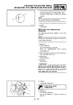
Страница 446: ...9 2 POOR MEDIUM AND HIGH SPEED PERFORMANCE 9 3 ENGINE 9 3 FUEL SYSTEM 9 3 FAULTY GEAR SHIFTING 9 3 SHIFTING IS DIFFICULT 9 3 SHIFT PEDAL DOES NOT MOVE 9 3 JUMPS OUT OF GEAR 9 3 FAULTY CLUTCH 9 3 CLUTCH SLIPS 9 3 CLUTCH DRAGS 9 3 OVERHEATING 9 4 ENGINE 9 4 COOLING SYSTEM 9 4 FUEL SYSTEM 9 4 CHASSIS 9 4 ELECTRICAL SYSTEMS 9 4 OVERCOOLING 9 4 COOLING SYSTEM 9 4 POOR BRAKING PERFORMANCE 9 4 ...

Страница 447: ...HTING OR SIGNALING SYSTEM 9 6 HEADLIGHT DOES NOT LIGHT 9 6 HEADLIGHT BULB BURNT OUT 9 6 TAIL BRAKE LIGHT DOES NOT LIGHT 9 6 TAIL BRAKE LIGHT BULB BURNT OUT 9 6 TURN SIGNAL DOES NOT LIGHT 9 6 TURN SIGNAL BLINKS SLOWLY 9 6 TURN SIGNAL REMAINS LIT 9 6 TURN SIGNAL BLINKS QUICKLY 9 6 HORN DOES NOT SOUND 9 6 ...

Страница 448: ...perly installed piston ring Damaged worn or fatigued piston ring Seized piston ring Seized or damaged piston Air filter Improperly installed air filter Clogged air filter element Crankcase and crankshaft Improperly assembled crankcase Seized crankshaft FUEL SYSTEM Fuel tank Empty fuel tank Clogged fuel filter Clogged fuel strainer Clogged fuel tank drain hose Clogged rollover valve Clogged rollove...

Страница 449: ...em Faulty starter motor Faulty starter relay Faulty starting circuit cutoff relay Faulty starter clutch EAS00846 INCORRECT ENGINE IDLING SPEED ENGINE Cylinder s and cylinder head s Incorrect valve clearance Damaged valve train components Air filter Clogged air filter element FUEL SYSTEM Carburetor s Faulty starter plunger Loose or clogged pilot jet Loose or clogged pilot air jet Damaged or loose c...

Страница 450: ...sembled transmission JUMPS OUT OF GEAR Shift shaft Incorrect shift pedal position Improperly returned stopper lever Shift forks Worn shift fork Shift drum Incorrect axial play Worn shift drum groove Transmission Worn gear dog EAS00852 FAULTY CLUTCH CLUTCH SLIPS Clutch Improperly assembled clutch Improperly assembled clutch master cylin der Improperly assembled clutch release cylin der Incorrect cl...

Страница 451: ...nnected hose Damaged pipe Improperly connected pipe FUEL SYSTEM Carburetor s Incorrect main jet setting Incorrect fuel level Damaged or loose carburetor joint Air filter Clogged air filter element CHASSIS Brake s Dragging brake ELECTRICAL SYSTEMS Spark plug s Incorrect spark plug gap Incorrect spark plug heat range Ignition system Faulty ignitor unit EAS00856 OVERCOOLING COOLING SYSTEM Thermostat ...

Страница 452: ...nt or improperly installed handlebar Steering head components Improperly installed upper bracket Improperly installed lower bracket improp erly tightened ring nut Bent steering stem Damaged ball bearing or bearing race Front fork leg s Uneven oil levels both front fork legs Unevenly tensioned fork spring both front fork legs Broken fork spring Bent or damaged inner tube Bent or damaged outer tube ...

Страница 453: ...LB BURNT OUT Wrong tail brake light bulb Faulty battery Incorrectly adjusted rear brake light switch Tail brake light bulb life expired TURN SIGNAL DOES NOT LIGHT Faulty turn signal switch Faulty turn signal relay Burnt out turn signal bulb Incorrect connection Damaged or faulty wire harness Improperly grounded circuit Faulty battery Blown damaged or incorrect fuse TURN SIGNAL BLINKS SLOWLY Faulty...

Страница 454: ... switch 2 Rectifier regulator 3 Generator 4 Main fuse 5 Battery 6 Starter relay 7 Starter motor 8 Starting circuit cutoff relay 9 Right handlebar switch 0 Front brake light switch A Light switch B Engine stop switch C Start switch D Fuel reserve switch E Sidestand switch F Fuel pump relay G Fuel pump H Vacuum pressure sensor I Ignitor unit J Ignition coil K Spark plug L Pickup coil M Meter assembl...

Отзывы: