8 - 6
–
+
ELEC
EAS00732
CHECKING THE BULBS AND
BULB SOCKETS
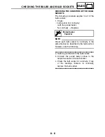
Check each bulb and bulb socket for damage
or wear, proper connections, and also for con-
tinuity between the terminals.
Damage/wear
→
Repair or replace the
bulb, bulb socket or both.
Improperly connected
→
Properly connect.
No continuity
→
Repair or replace the bulb,
bulb socket or both.
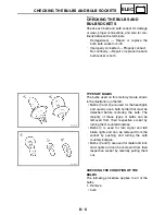
TYPES OF BULBS
The bulbs used on this motorcycle are shown
in the illustration on the left.
• Bulbs
A
and
B
are used for the headlights
and usually use a bulb holder that must be
detached before removing the bulb. The
majority of these types of bulbs can be
removed from their respective socket by
turning them counterclockwise.
• Bulbs
C
is used for turn signal and tail/
brake lights and can be removed from the
socket by pushing and turning the bulb
counterclockwise.
• Bulbs
D
and
E
are used for meter and indi-
cator lights and can be removed from their
respective socket by carefully pulling them
out.
CHECKING THE CONDITION OF THE
BULBS
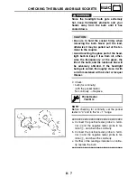
The following procedure applies to all of the
bulbs.
1. Remove:
• bulb
CHECKING THE BULBS AND BULB SOCKETS
Содержание FJR1300
Страница 1: ...LIT 11616 16 18 5JW 28197 10 FJR1300R FJR1300RC SERVICE MANUAL ...
Страница 6: ......
Страница 82: ...2 22 SPEC TIGHTENING TORQUES Cylinder head tightening sequence Crankcase tightening sequence ...
Страница 89: ...2 29 SPEC 1 Crankshaft 2 Main axle 3 Drive axle OIL FLOW DIAGRAMS ...
Страница 90: ...2 30 SPEC 1 Oil nozzle 2 Main gallery bolt 3 Crankshaft OIL FLOW DIAGRAMS ...
Страница 91: ...2 31 SPEC 1 Main axle 2 Drive axle 3 Oil delivery pipe OIL FLOW DIAGRAMS ...
Страница 92: ...2 32 SPEC 1 Exhaust camshaft 2 Oil check bolt 3 Intake camshaft OIL FLOW DIAGRAMS ...
Страница 93: ...2 33 SPEC 1 Oil check bolt 2 Crankshaft 3 Oil cooler 4 Oil pump 5 Oil strainer 6 Oil pipe OIL FLOW DIAGRAMS ...
Страница 94: ...2 34 SPEC 1 Crank pin 2 Crankshaft OIL FLOW DIAGRAMS ...
Страница 95: ...2 35 SPEC 1 Rear balancer 2 Oil delivery pipe 3 Crankshaft 4 Front balancer 5 Crank pin OIL FLOW DIAGRAMS ...
Страница 97: ...2 37 SPEC 1 Main axle 2 Drive axle 3 Middle drive shaft OIL FLOW DIAGRAMS ...
Страница 98: ...2 38 SPEC COOLING SYSTEM DIAGRAMS 1 Radiator COOLING SYSTEM DIAGRAMS ...
Страница 99: ...2 39 SPEC 1 Water jacket joint 2 Oil cooler COOLING SYSTEM DIAGRAMS ...
Страница 100: ...2 40 SPEC 1 Thermostat assembly 2 Coolant reservoir 3 Radiator 4 Oil cooler COOLING SYSTEM DIAGRAMS ...
Страница 101: ...2 41 SPEC 1 Coolant reservoir 2 Radiator 3 Water pump COOLING SYSTEM DIAGRAMS ...
Страница 107: ...2 47 SPEC CABLE ROUTING 1 Tail brake light lead ...
Страница 196: ...3 80 CHK ADJ ADJUSTING THE HEADLIGHT BEAMS ...
Страница 288: ...4 92 CHAS 3 Install bearing 1 to the swingarm Installed depth a 4 0 mm 0 16 in SWINGARM ...
Страница 531: ...8 35 ELEC LIGHTING SYSTEM ...
Страница 570: ......
Страница 571: ...YAMAHA MOTOR CO LTD 2500 SHINGAI IWATA SHIZUOKA JAPAN PRINTED IN U S A ...

